PWM,脈寬調制,首先明確它不是STM32的標準外設,也沒有對應的庫函數和寄存器,不像ADC,SPI,CAN,USART等屬于外設可以直接調用.C文件進行驅動,PWM是一種脈寬調制機制,是模擬轉數字或數字轉模擬的一種控制方式,它無非輸出的就是0和1,只是利用輸出0和1的時間長短來應對模擬量的變化,具體講解還需詳細了解PWM.那么STM32是利用定時器產生PWM的,STM32 定時器非常強大,其中上篇文章提到的SYSTICK也是定時器的一種,先上一段我編寫的程序與大家分享,有什么不對的歡迎大家指點迷津。(現在開始慢慢都用函數寫程序了,顯得有層次。)
題目:用STM32的 TIM3產生四路PWM輸出,占空比任意即可。
#include "stm32f10x_conf.h"
void GPIO_CFG(void);
void RCC_CFG(void);
void TIM_CFG(void);
int main (void)
{
RCC_CFG();
GPIO_CFG();
TIM_CFG();
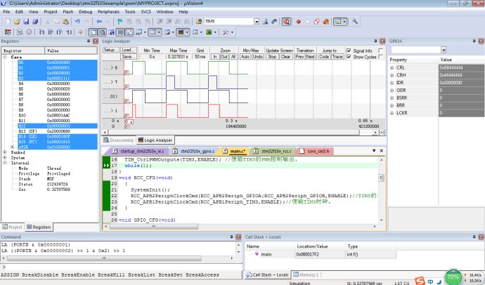
TIM_Cmd(TIM3,ENABLE);
TIM_CtrlPWMOutputs(TIM3,ENABLE);
while(1);
}
void RCC_CFG(void)
{
SystemInit();
RCC_APB2PeriphClockCmd(RCC_APB2Periph_GPIOA|RCC_APB2Periph_GPIOB,ENABLE);
RCC_APB1PeriphClockCmd(RCC_APB1Periph_TIM3,ENABLE);
}
void GPIO_CFG(void)
{
GPIO_InitTypeDef GPIO_InitStructure;
GPIO_InitStructure.GPIO_Pin=GPIO_Pin_6|GPIO_Pin_7;
GPIO_InitStructure.GPIO_Speed=GPIO_Speed_50MHz;
GPIO_InitStructure.GPIO_Mode=GPIO_Mode_AF_PP;
GPIO_Init(GPIOA,&GPIO_InitStructure);
GPIO_InitStructure.GPIO_Pin=GPIO_Pin_0|GPIO_Pin_1;
GPIO_InitStructure.GPIO_Speed=GPIO_Speed_50MHz;
GPIO_InitStructure.GPIO_Mode=GPIO_Mode_AF_PP;
GPIO_Init(GPIOB,&GPIO_InitStructure);
}
void TIM_CFG(void)
{
TIM_TimeBaseInitTypeDef TIM_TimeBaseStructure;
TIM_OCInitTypeDef TIM_OCInitStructure;
TIM_TimeBaseStructure.TIM_Period=2000;
TIM_TimeBaseStructure.TIM_Prescaler=35999;
TIM_TimeBaseStructure.TIM_ClockDivision=0x00;
TIM_TimeBaseStructure.TIM_CounterMode=TIM_CounterMode_Up;
TIM_TimeBaseStructure.TIM_RepetitionCounter=0x00;
TIM_TimeBaseInit(TIM3,&TIM_TimeBaseStructure);
TIM_OCInitStructure.TIM_OCMode=TIM_OCMode_PWM1;
TIM_OCInitStructure.TIM_Pulse=1000;
TIM_OCInitStructure.TIM_OCPolarity=TIM_OCPolarity_High;
TIM_OCInitStructure.TIM_OutputState=TIM_OutputState_Enable;
TIM_OC1Init(TIM3,&TIM_OCInitStructure);
TIM_OCInitStructure.TIM_Pulse=400;
TIM_OC2Init(TIM3,&TIM_OCInitStructure);
TIM_OCInitStructure.TIM_Pulse=1000;
TIM_OC3Init(TIM3,&TIM_OCInitStructure);
TIM_OCInitStructure.TIM_Pulse=550;
TIM_OC4Init(TIM3,&TIM_OCInitStructure);
}
有疑問可以給我留言。
