|
電子信息技術綜合實訓報告 競賽題名稱:基于C語言的89C51與TLC2543AD轉換器的驅動程序的設計 隊員名稱: 評閱人簽名: 設計思路: 硬件部分基于80C51單片機和TLC2543組成多路數據采集系統,采用89C51作為控制部件,控制數據的采集、顯示、傳輸,它是整個系統的核心。由TLC2543作為此數據采集系統的A/D轉換芯片,進行模數轉換得到模擬信號測量值,它使用開關電容逐次逼近技術完成A/D轉換過程由于是串行輸入結構,能夠節省51系列單片機的I/O資源。硬件設計的主要任務是TLC2543和單片機的接口電路設計,輸入信號的調理電路設計。 軟件部分主要涉及A/D轉換程序的編寫,1602LCD驅動的編寫,從TLC2543所接收數據的處理等。 原理框圖:見圖1。

圖1 模數轉換系統框圖 由ProteusEDA工具軟件所繪制原理圖,見圖2。
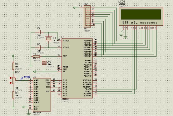 圖2 模數轉換系統原理圖
 算法1: for(i=0;i<6;i++) { ad_result=AD_Conver(0); sum+=ad_result; } ad=sum*5.0/4096/6; 說明:對TLC2543的返回值ad_result進行求和,然后取平均數。 算法2: num[0]=ad_result/10000+'0'; num[2]=ad_result%10000/1000+'0'; num[3]=ad_result%1000/100+'0'; num[4]=ad_result%100/10+'0'; num[5]=ad_result%10+'0'; 說明:分別求出LCD顯示數值各位的數值。 1602LCD程序流程圖,見圖3。

圖3 1602LCD程序流程圖 主程序流程圖,見圖4。
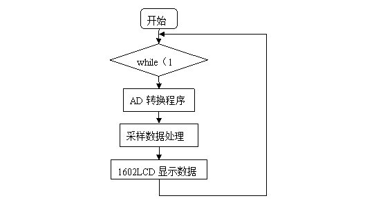
圖4 主程序流程圖 由探針對模擬信號輸入端口進行電壓測量,數值為2.71192V,見圖5。
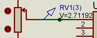
圖5 對模擬信號采樣并處理,得模擬信號輸入端口電壓測量值為2.7111V,見圖6。
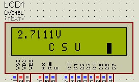
圖6 滑動滑動變阻器改變模擬輸入端口電壓,共測得數據5組數據,見表1。 表1 測試數據分析:
 =0.0008
 =0.0001
 =0.0012 (舍去)
 =0.0002
 =0.0005
 誤差平均值:+++
 0.0008
 結論:由以上計算結果可知,該系統誤差較小,能滿足日常所需的測量精度要求,同時反映出TLC2543模數轉換芯片具有誤差小,分辨率較高,因此在儀器儀表中有較為廣泛的應用。 附件一:程序源代碼 - #include<reg51.h>
- #include<intrins.h>
- #define uchar unsigned char
- #define uint unsigned int
- sbit RS=P3^5;
- sbit RW=P3^6;
- sbit E=P3^4;
- sbit BF=P0^7; //1602忙碌標志位
- void delay1ms()
- {uchar i,j;
- for(i=0;i<10;i++)
- for(j=0;j<33;j++)
- ; }
- void delay(uchar n) //延時n毫秒
- {uchar i;
- for(i=0;i<n;i++)
- delay1ms();}
- unsigned char BusyTest(void) //result=1為忙碌;result=0為不忙碌
- {bit result;
- RS=0;
- RW=1; //高電平進行讀操作
- E=1; //E=1,才允許讀寫
- _nop_();
- _nop_();
- _nop_();
- _nop_();
- result=BF;
- E=0;
- return result;}
- void WriteInstruction (uchar dictate) //寫指令
- { while(BusyTest()==1);
- RS=0; //RS和R/W同時為低電平時,可以寫入指令
- RW=0;
- E=0;
- _nop_();
- _nop_();
- P0=dictate;
- _nop_();
- _nop_();
- _nop_();
- _nop_();
- E=1;
- _nop_();
- _nop_();
- _nop_();
- _nop_();
- E=0;}
- void WriteAddress(uchar x) //寫地址
- {WriteInstruction(x|0x80); //顯示位置的確定方法規定為"80H+地址碼x"
- }
- void WriteData(uchar y)
- { while(BusyTest()==1);
- RS=1; //RS為高電平,RW為低電平時,寫入數據
- RW=0;
- E=0;
- P0=y;
- _nop_();
- _nop_();
- _nop_();
- _nop_();
- E=1;
- _nop_();
- _nop_();
- _nop_();
- _nop_();
- E=0;}
- void LcdInitiate(void) //初始化
- {delay(15);
- WriteInstruction(0x38); //顯示模式設置:16×2顯示,5×7點陣,8位數據接口
- delay(5);
- WriteInstruction(0x38);
- delay(5);
- WriteInstruction(0x38);
- delay(5);
- WriteInstruction(0x0f); //顯示模式設置:顯示開,有光標,光標閃爍
- delay(5);
- WriteInstruction(0x06); //顯示模式設置:光標右移,字符不移
- delay(5);
- WriteInstruction(0x01); //清屏幕指令,將以前的顯示內容清除
- delay(5);}
- sbit CLOCK=P1^3;
- sbit DATA_IN=P1^1;
- sbit DATA_OUT=P1^0;
- sbit CS=P1^2;
- void delay1()
- {int i=5;
- while(i--);}
- uint AD_Conver(uchar channel) //選擇輸入通道
- {uchar i;
- int ad_value=0;
- CLOCK=0;
- CS=1;
- delay1();
- CS=0;
- channel<<=4; //左移4位
- for(i=0;i<12;i++)
- { if(DATA_OUT)ad_value|=1;
- DATA_IN=(bit)(channel&0x80);
- CLOCK=1;
- delay1();
- CLOCK=0;
- channel<<=1;
- ad_value<<=1;}
- CLOCK=1;
- ad_value>>=1;
- return ad_value; //返回轉換數據
- }
- void main()
- { int ad_result;
- uint i;
- float ad;
- uint num[]={'0','.','0','0','0','0','V',' ',' ',' ',' ',' '};
- uint csu[]={' ',' ',' ',' ',' ','C',' ','S',' ','U',' ',' ',' ',' ',' '};
- ad_result=AD_Conver(0);
- delay(100);
- while(1)
- {uint sum;
- sum=0;
- for(i=0;i<6;i++)
- {
- ad_result=AD_Conver(0);
- sum+=ad_result;}
- ad=sum*5.0/4096/6; //4096為2的12次方,6為求平均數
- ad_result=(int)(ad*10000); //轉換為整形變量
- num[0]=ad_result/10000+'0';
- num[2]=ad_result%10000/1000+'0';
- num[3]=ad_result%1000/100+'0';
- num[4]=ad_result%100/10+'0';
- num[5]=ad_result%10+'0';
- LcdInitiate();
- WriteAddress(0x80); //第一行第一列顯示
- for(i=0;i<15;i++)
- {WriteData(num[i]);
- delay(850);}
- WriteAddress(0xc0); //第二行第一列顯示
- for(i=0;i<15;i++)
- {WriteData(csu[i]);
- delay(850);}
- delay(10000);}
- }
-
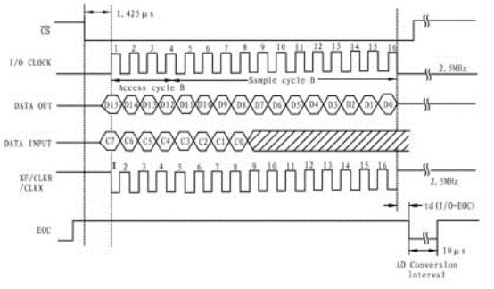
附件二:TLC2543時序圖
完整版本的論文請下載附件:
|