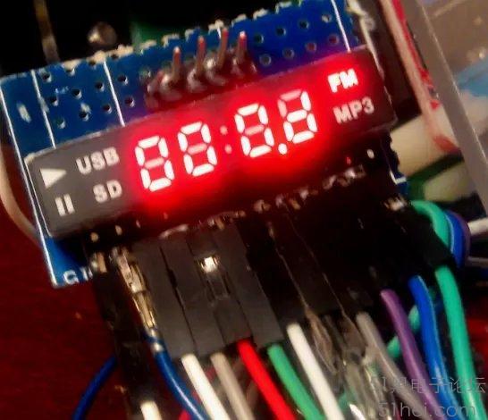
經過諸多嘗試,終于把這個LED數碼管的顯示方式搞清楚了。該數碼管的面板和管腳結構表示如下:

該數碼管共12個管腳,Pin1-7為數碼管的A-G段,Pin8-11對應于中間四個數字字符,從左到右分別編為D1-D4,Pin12對應于邊上的其它符號。
從左上角排列,分別與Pin1-Pin7對應的Play, Pause, USB, SD, TDP(時間顯示的兩個點),FM(包括后面:8.8中間的點,以及最后的MP3)。
從字符選擇D1-D5端提高高電平,而SEGA-SEGG則為低電平,從而點亮對應的字符。對應關系如上圖所示。
對應于0-9,A-F的字模編碼如下:
#define LED_ON 1
#define LED_OFF 0
unsigned char cp;
unsigned char dispPtr;
static unsigned char code CharCode[] = {
//共陽極 共陰極 0 G F E D C B A 字符值
0x40, //0x3F, // 0 0 1 1 1 1 1 1 0x3F:0
0x79, //0x06, // 0 0 0 0 0 1 1 0 0x06:1
0x24, //0x5B, // 0 1 0 1 1 0 1 1 0x5B:2
0x30, //0x4F, // 0 1 0 0 1 1 1 1 0x4F:3
0x19, //0x66, // 0 1 1 0 0 1 1 0 0x66:4
0x12, //0x6D, // 0 1 1 0 1 1 0 1 0x6D:5
0x02, //0x7D, // 0 1 1 1 1 1 0 1 0x7D:6
0x78, //0x07, // 0 0 0 0 0 1 1 1 0x07:7
0x00, //0x7F, // 0 1 1 1 1 1 1 1 0x7F:8
0x10, //0x6F, // 0 1 1 0 1 1 1 1 0x6F:9
0x08, //0x77, // 0 1 1 1 0 1 1 1 0x77:A
0x03, //0x7C, // 0 1 1 1 1 1 0 0 0x7C:b
0x27, //0x58, // 0 1 0 1 1 0 0 0 0x58:c
0x21, //0x5E, // 0 1 0 1 1 1 1 0 0x5E:d
0x06, //0x79, // 0 1 1 1 1 0 0 1 0x79:E
0x0E, //0x71, // 0 1 1 1 0 0 0 1 0x71:F
//0x01, //bPlay;
//0x02, //bPause;
//0x04, //bUSB;
//0x08, //bSD;
//0x10, //bTDP;
//0x20, //bFM;
//0x40, //bMP3;
//0x00 //bBlank;
};
利用定時器中斷 Timer0來進行顯示。其中Disp程序是將對應的字形碼輸出到數碼管所接的端口的。
這里定義了一個結構,用來表示LED要顯示的內容(其實不是必要的)。
struct DispBuf {
int bPLAY:1;
int bPAUSE:1;
int bUSB:1;
int bSD:1;
int bTDP:1;
int bFM:1;
int bMP3:1;
unsigned char DBuf[4];
};
struct DispBuf theBuf;
void Disp(unsigned char c);
void Timer0_isr(void) interrupt 1
{
cp++;
//以下進行各數碼管分時掃描。
if (cp == 3) { //5ms * 4 = 20ms LED_REFRESH_FREQ 拖過調整顯示延遲常數,
//可以改變顯示時 LED的閃爍狀態,越小速度越快,閃爍越低,但是耗電可能會增加。
cp =0;
dispPtr++;
if (dispPtr ==1) {
D5=LED_OFF;
Disp(CharCode[theBuf.DBuf[0]]);
D1=LED_ON;
}
if (dispPtr ==2) {
D1=LED_OFF;
Disp(CharCode[theBuf.DBuf[1]]);
D2=LED_ON;
}
if (dispPtr ==3) {
D2=LED_OFF;
Disp(CharCode[theBuf.DBuf[2]]);
D3=LED_ON;
}
if (dispPtr ==4) {
D3=LED_OFF;
Disp(CharCode[theBuf.DBuf[3]]);
D4=LED_ON;
}
if (dispPtr ==5) {
D4=LED_OFF;
Disp(0xFF); //對于各種符號的顯示做特殊處理。
D5=LED_ON;
dispPtr=0;
}
}
}
void Disp(unsigned char c)
{
unsigned char t;
t= c;
if (c == 0xFF) { //附加的各種符號的判定和顯示,需要合并。
if (theBuf.bPLAY == 0) t |= 0x01; else t &= 0xFE;
if (theBuf.bPAUSE == 0) t |= 0x02; else t &= 0xFD;
if (theBuf.bUSB == 0) t |= 0x04; else t &= 0xFB;
if (theBuf.bSD == 0) t |= 0x08; else t &= 0xF7;
if (theBuf.bTDP == 0) t |= 0x10; else t &= 0xEF;
if (theBuf.bFM == 0) t |= 0x20; else t &= 0xDF;
if (theBuf.bMP3 == 0) t |= 0x40; else t &= 0xBF;
}
P2 &= 0xE0; //清除低5位:SEGA-SEGE連接至P2^0 - P2^4
P2 |= (t & 0x1F);
P4 &= 0x9F; //清除 P4.5, P4.6; SEGF,SEGG連接至 P4^5和P4^6.
P4 |= (t & 0x60);
}
實用的顯示整數的子程序。最大顯示的四位數0-0xFFFF。
void DispHInt(unsigned int nNum)
{
unsigned int t;
//將整數拆分為16進制數,分別送到對應的字符緩沖區中。
t=nNum/0x1000;
theBuf.DBuf[0]=t;
t=(nNum%0x1000)/0x100;
theBuf.DBuf[1]=t;
t=(nNum%0x100)/0x10;
theBuf.DBuf[2]=t;
t=nNum%0x10;
theBuf.DBuf[3]=t;
}
//演示例程。需要添加到main函數中使用。
void ScanLED()
{
unsigned int i;
theBuf.bFM=1; //顯示FM標志
theBuf.bPLAY =0;
theBuf.bPAUSE =0;
theBuf.bSD =0;
theBuf.bUSB =0;
theBuf.bTDP =0;
theBuf.bMP3 =0;
for (i=0;i<0xFFFF;i++)
{
DispHInt(i);
delay(10); //延時程序,未列出。
}
}
以上程序在 STC15W4K32S4 LQ44的樣機上調試通過。運行效果如下:
|


 QQ好友和群
 QQ空間
QQ空間 騰訊微博
騰訊微博 騰訊朋友
騰訊朋友 收藏
收藏 淘帖
淘帖 頂
頂 踩
踩

