最近使用了一款Cortex-M0內核的芯片STM32F030CC,發現它中斷向量表的重映射方法與STM32F10x系列的有所區別,在這里記錄與分享一下。
由于需要通過IAP進行固件升級,所以芯片的FLASH里面要燒錄兩份代碼:一個Boot loader, 一個用戶應用程序。理所當然的,在用戶應用程序中,必須得重新映射中斷向量表。 可是在ST提供的固件庫里,我卻沒有發現類似于stm32f10x固件庫中的voidNVIC_SetVectorTable(uint32_t NVIC_VectTab, uint32_t Offset)接口。 瀏覽了一下Cortex-M0的Programmingmanual,原來M0并沒有SCB->VTOR這個寄存器,難怪ST的庫里沒有提供NVIC_SetVectorTable這個接口。 這下要怎么辦?在網絡上搜索了一下,受到網友findaway123這篇文章的啟發,我在STM32F030CC的Reference manual中找到以下說明: Physicalremap Once the boot mode is selected, the application software canmodify the memory accessible in the code area.This modification isperformed by programming the MEM_MODE bits in the SYSCFGconfiguration register 1 (SYSCFG_CFGR1). Unlike Cortex? M3 and M4,the M0 CPU does not support the vector table relocation. Forapplication code which is located in a different address than0x0800 0000, some additional code must be added in order to be ableto serve the application interrupts. A solution will be to relocateby software the vector table to the internal SRAM: ? Copy the vector table from the Flash (mapped at the base of theapplication load address) to the base address of the SRAM at 0x20000000. ? Remap SRAM at address 0x0000 0000, using SYSCFG configurationregister 1. ? Then once an interrupt occurs, the Cortex?-M0 processor willfetch the interrupt handler start address from the relocated vectortable in SRAM, then it will jump to execute the interrupt handlerlocated in the Flash. This operation should be done at the initialization phase of theapplication. Please refer to AN4065 and attached IAP codefrom www.st.com for more details. OK,解決方法找到了!
在用戶應用程序中,按照以上方法,添加以下兩行代碼: memcpy((void*)0x20000000, (void*)0x08004000, VECTOR_SIZE); SYSCFG_MemoryRemapConfig(SYSCFG_MemoryRemap_SRAM);
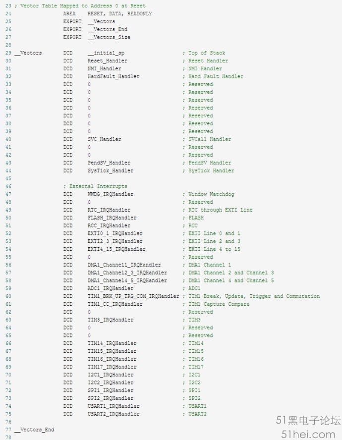
其中,0x2000 0000是SRAM的起始地址,這個不需要改動。 而之后的兩個參數需要根據實際情況作出修改。0x08004000是應用程序的起址地址,從這里開始的VECTOR_SIZE字節,存放是的應用程序的中斷向量表。VECTOR_SIZE是指中斷向量表的大小,具體多大可以在startup.s文件里計算得到。以下以startup_stm32f030.s為例作說明: 我們只需關注其中的一小部分。從29行開始,直到75行,每一個DCD都代表一個中斷向量(所謂中斷向量,說得明白點,其實就是某個中斷服務程序的入口地址)。例如第74行的: DCD USART1_IRQHandler ; USART1 這里的“USART1_IRQHandler"其實就是UART1中斷服務程序USART1_IRQHandler這個函數,同時,它也代表這個函數的入口地址。 以上代碼即定義了這樣一張表,這張表包括45個元素,每個元素是一個長度為4字節的地址。除了第一個地址是SP(堆棧指針)外,其它的地址都是某個中斷服務程序的入口地址。 那么,回到我們要解決的問題上來,之前memcpy函數中的第三個參數VECTOR_SIZE,針對本例,就應該是45*4=180(0xB4)個字節。
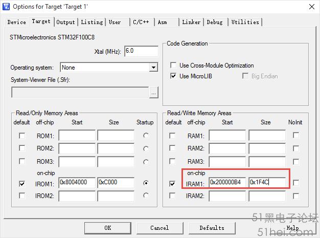
在執行完以上兩行代碼后,若發生中斷,CPU就會去SRAM(即0x2000 0000處)取中斷向量了,所以,以0x20000000作為起始地址之后的VECTOR_SIZE個字節就不能被改動了。為了達到這VECTOR_SIZE個字節不被修改的目的,如下兩種方法可以實現。 ?在工程文件內修改SRAM的起始地址及長度,如下圖 ?如果使用了分散加載文件,則在分散加載文件中修改SRAM的起始地址及長度也能達到目的。
至此,STM32F0系列Cortex-M0內核芯片中斷向量表重映射的問題已解決。
| 


 QQ好友和群
 QQ空間
QQ空間 騰訊微博
騰訊微博 騰訊朋友
騰訊朋友 收藏
收藏 淘帖
淘帖 頂
頂 踩
踩


