|
|
對講機應該焊接的差不多了,但是了解原理甚至比焊接更困難。 當時學習模電之類的學的就馬馬虎虎,感覺不是很懂。
http://www點zen22142.zen點co點uk/Circuits/rf/amrec.html
這個網絡上的資料仿真了一個AM收音機,可以參考一下。其實對講機也可以認為是一個FM收音機的簡化版,只收聽一個頻率。
這個資料解釋的更過一點,可以仔細看看。
http://www點vintage-radio點com/repair-restore-information/transistor_if-rf-stages.html
但是還是不太理解,于是仔細看了別人的討論感覺蠻困難的。
http://forums點anandtech點com/showthread.php?t=286537
這個網址也不錯,分析了這種電路,非常類似:
http://www點sentex點ca/~mec1995/tutorial/xtor/xtor7/xtor7.html
這個電路的歷史已經100年了。
https://en點wikipedia點org/wiki/Regenerative_circuit
和https://en點wikipedia點org/wiki/Regenerative_circuit
這個資料也可以參考:
http://members點iinet點net點au/~cool386/6tr/srrx.html
http://www點somerset點net/arm/fm_only_lowtech.html
這個電路中文資料也沒有找到,只有這個
http://www點wendangku點net/doc/561f2887ec3a87c24028c410.html
試著分析一下,由文中知道電容C4為正反饋,形成振蕩電路。是所謂“起到靈敏度極高的超再生檢波作用”!
后面的放大電路,應該簡單一點,但是也不太明白。
開始試著使用MultiSim仿真。
 這個是從網上找的原理圖,和我們的一樣,需要在最下面一行增加接地符號! 這個是從網上找的原理圖,和我們的一樣,需要在最下面一行增加接地符號!
然后開始仿真,將這個圖分成兩個部分,一個為發射部分,一個為接收部分。在接收狀態下,R6、C7、C8就沒有了。
處于發射狀態,則C14、C6就沒有了,電路的拓撲也要發生變化。
還有一個問題是天線,各個器件如何選取。由于涉及振蕩電路,還是蠻難的。可惜當年學藝不精啊!
繼續:
昨天用了一個小時才畫了了一點原理圖。
今天發現應該用粘貼的方法,將原件復制,不用每次到元件庫修改,并且注意Ctrl + R等快鍵鍵調整原件方向;其次,沒有的原件,比如C9018,用虛擬的原件代替,然后根據器件手冊,修改參數。具體實現方法在http://www點eng點auburn.edu/~niuguof/multisimdev/bjt.html 還有就是如何估算,電感線圈的值:收音機的書38頁。

又: 今天下午,又仔細看了一下原理,希望徹底搞懂。發現了兩個有用的資源: (1)http://www點talkingelectronics點com/projects/27MHz%20Transmitters/27MHzLinks-1.html#THE 27MHz TRANSMITTER 其中一個27M的振蕩器,和我們使用的非常類似,并且作者給出了簡單的解釋: 2. THE RECEIVER FRONT END
The front end of a 27MHz receiver is slightly different to the front end of a 27MHz Walkie Talkie. The circuit is very lightly loaded so that it will detect the slightest signal and this makes it very sensitive.
The component that does this is the 3k9 in the power rail.
The transistor has only about 2v across it and takes less than 1mA.
The circuit is a common-base amplifier and under certain circumstances, a single transistor in this configuration will oscillate.
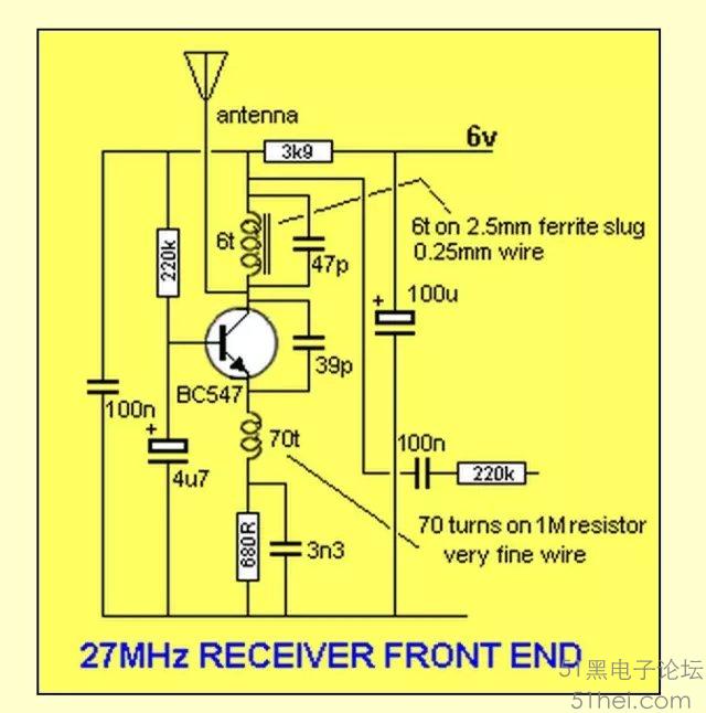
First, let's describe how a common-base stage works. The 220k base-bias resistor turns the stage on. The coil in the collector is the load but since it is such a low resistance, a voltage-dropping resistor has to be placed in the emitter. This resistor only limits the current through the circuit. It is by-passed with a 3n3 capacitor and does not cone into the operation of the operation of the circuit. There are two ways to turn on a transistor. one is to hold the emitter fixed and deliver a voltage and current to the base. The other is to hold the base rigid and reduce the voltage on the emitter. that is what we have done in this circuit. The 4u7 electrolytic on the base holds it rigid and the 39p reduces the voltage on the emitter to turn the transistor ON and during the other part of the 27MHz cycle, it increases the voltage on the emitter to turn it OFF. This concept must be understood before we can advance further. The circuit starts by receiving a pulse of current through the 6t coil and 47p capacitor, when it is turned on. These two components form a TUNED CIRCUIT and when they receive energy, they produce a sine-wave (sinusoidal) waveform that appears on the lower part of the tank circuit and this is passed to the emitter via the 39p. It's an amazing fact that two simple components can produce a sinewave that has an amplitude larger than the voltage applied to the pair, but this is what happens and to fully explain it, would require another chapter. However the end result is the emitter is pushed down to turn the transistor ON more and pulled up to turn it off. The 70t inductor on the emitter simply keeps it away from the 0v rail so that the pulses on the 39p can have an effect on pushing and pulling the emitter. To explain how the inductor works is very difficult, however it has the effect of allowing the 39p to push the voltage lower on the emitter, than if it were not included. If the inductor is removed, the 39p will have a very hard job to push against the 3n3. But if the 3n3 is removed the 39p will have a small difficulty pushing against the effect of the 680R. However when the inductor is added, the 39p has a much easier job of pushing and pulling the emitter. Even though this is the front end of a receiver, it is actually oscillating at 27MHz. The circuit has been built for experiential purposes to make sure the 70t inductor and 6t coil work perfectly to price a sensitive front-end. Never put a circuit on the web without building and testing it with actual components. Simulation programs cannot predict the outcome of hand-made components. The 70t inductor is about 7uH and is wound on a 1M resistor with very fine wire. The resistor can be any high value and does not play a part in the functioning of the circuit. It is just a convenient core for the winding. The carbon content of the resistor does not have any effect on the inductance.
具體計算27M的頻率是,由6t的電感值和47p決定的,公式是粘貼在matlab命令窗口:
>> L=0.6*10^(-6); >> C=47*10^(-12); >> f=1/(2*pi*sqrt(L*C)) f = 2.9971e+007
6t的線圈的電感估計為0.6uH, (The 70t inductor is about 7uH,我是根據這個推算的,可能不準).
進一步參考電感計算網站,計算公式和說明http://www點eeweb點com/toolbox/coil-inductance/
仿真時,碰到幾個三極管具體沒有需要自己輸入參數,或者找到替代的三極管。這個網站會有幫助:
http://alltransistors點com/transistor.php?transistor=21057
這個電路確實不太好理解,看了這篇文章我有點釋然,很多RF工程師也犯難啊!
http://www點eix.co點uk/Articles/Radio/Welcome.htm
|
|


 QQ好友和群
 QQ空間
QQ空間 騰訊微博
騰訊微博 騰訊朋友
騰訊朋友 收藏
收藏 淘帖
淘帖 頂
頂 踩
踩

