|
|
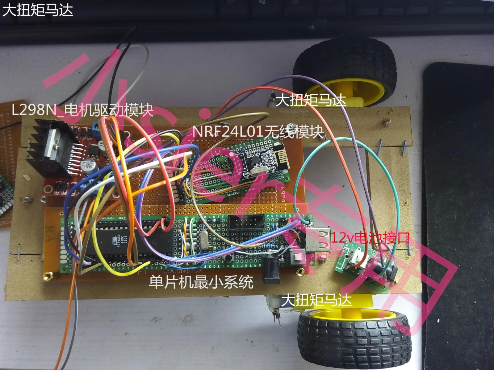
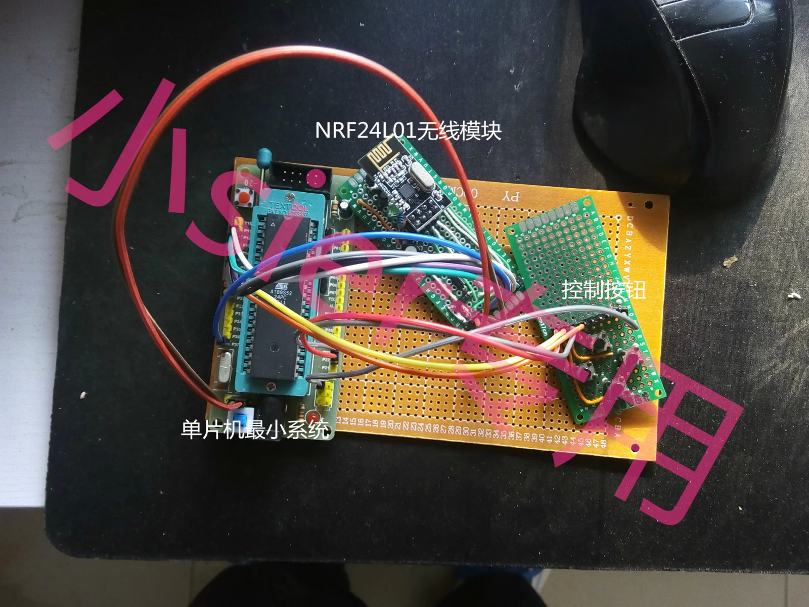
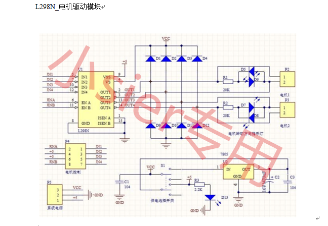
直接上圖:
以下是編譯后的收發一體程序可以自行更改:
1.無線子程序文件nRF24L01.h
// nRF24L01.h
#ifndef _NRF_24L01_
#define _NRF_24L01_
#define TX_ADR_WIDTH 5 // 5 bytes TX address width
#define RX_ADR_WIDTH 5 // 5 bytes RX address width
#define TX_PLOAD_WIDTH 20 //20 bytes TX payload
#define RX_PLOAD_WIDTH 20 //20 bytes TX payload
typedef unsigned char BYTE;
typedef unsigned char uchar;
//****************************************************************//
// SPI(nRF24L01) commands
#define READ_REG 0x00 // Define read command to register
#define WRITE_REG 0x20 // Define write command to register
#define RD_RX_PLOAD 0x61 // Define RX payload register address
#define WR_TX_PLOAD 0xA0 // Define TX payload register address
#define FLUSH_TX 0xE1 // Define flush TX register command
#define FLUSH_RX 0xE2 // Define flush RX register command
#define REUSE_TX_PL 0xE3 // Define reuse TX payload register command
#define NOP 0xFF // Define No Operation, might be used to readstatus register
//***************************************************//
// SPI(nRF24L01) registers(addresses)
#define CONFIG 0x00 // 'Config' register address
#define EN_AA 0x01 // 'Enable Auto Acknowledgment' register address
#define EN_RXADDR 0x02 // 'Enabled RX addresses' register address
#define SETUP_AW 0x03 // 'Setup address width' register address
#define SETUP_RETR 0x04 // 'Setup Auto. Retrans' register address
#define RF_CH 0x05 // 'RF channel' register address
#define RF_SETUP 0x06 // 'RF setup' register address
#define STATUS 0x07 // 'Status' register address
#define OBSERVE_TX 0x08 // 'Observe TX' register address
#define CD 0x09 // 'Carrier Detect' register address
#define RX_ADDR_P0 0x0A // 'RX address pipe0' register address
#define RX_ADDR_P1 0x0B // 'RX address pipe1' register address
#define RX_ADDR_P2 0x0C // 'RX address pipe2' register address
#define RX_ADDR_P3 0x0D // 'RX address pipe3' register address
#define RX_ADDR_P4 0x0E // 'RX address pipe4' register address
#define RX_ADDR_P5 0x0F // 'RX address pipe5' register address
#define TX_ADDR 0x10 // 'TX address' register address
#define RX_PW_P0 0x11 // 'RX payload width, pipe0' register address
#define RX_PW_P1 0x12 // 'RX payload width, pipe1' register address
#define RX_PW_P2 0x13 // 'RX payload width, pipe2' register address
#define RX_PW_P3 0x14 // 'RX payload width, pipe3' register address
#define RX_PW_P4 0x15 // 'RX payload width, pipe4' register address
#define RX_PW_P5 0x16 // 'RX payload width, pipe5' register address
#define FIFO_STATUS 0x17 // 'FIFO Status Register' register address
//***************************************************************//
// FUNCTION's PROTOTYPES //
/****************************************************************/
// void SPI_Init(BYTE Mode); // Init HW or SW SPI
BYTESPI_RW(BYTE byte); // Single SPIread/write
BYTESPI_Read(BYTE reg); // Read one bytefrom nRF24L01
BYTESPI_RW_Reg(BYTE reg, BYTE byte); // Write one byte to register'reg'
BYTESPI_Write_Buf(BYTE reg, BYTE *pBuf, BYTE bytes); // Writes multiply bytes to one register
BYTESPI_Read_Buf(BYTE reg, BYTE *pBuf, BYTE bytes); // Read multiply bytes from one register
//*****************************************************************/
void inerDelay_us(unsigned char n);
void init_io(void) ;
void SetRX_Mode(void);
unsigned char nRF24L01_RxPacket(unsignedchar* rx_buf);
void nRF24L01_TxPacket(unsigned char *tx_buf);
extern uchar constTX_ADDRESS[TX_ADR_WIDTH];//TX address
extern uchar constRX_ADDRESS[RX_ADR_WIDTH];//;RX address
#endif //_NRF_24L01_
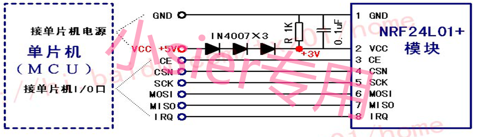
2.接口設定文件://def.h
#ifndef _DEF_
#define _DEF_
#include <reg52.h>
#include <intrins.h>
//hard pin mapping
sbit MISO =P1^3;
sbit MOSI =P1^4;
sbit SCK =P1^5;
sbit CE =P1^6;
sbit CSN =P3^7;
sbit IRQ =P1^2;
sbit LED2 =P3^5;
sbit LED1 =P3^4;
sbit LED3 =P3^6;
sbit LED4 =P3^7;
sbit KEY1 =P3^0;
sbit KEY2 =P3^1;
sbit KEY3 =P3^2;
sbit KEY4 =P3^3;
#endif //_DEF_
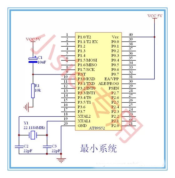
3.頭文件:REG52.H
#ifndef __REG52_H__
#define __REG52_H__
/* BYTE Registers */
sfr P0 = 0x80;
sfr P1 = 0x90;
sfr P2 = 0xA0;
sfr P3 = 0xB0;
sfr PSW = 0xD0;
sfr ACC = 0xE0;
sfr B = 0xF0;
sfr SP = 0x81;
sfr DPL = 0x82;
sfr DPH = 0x83;
sfr PCON = 0x87;
sfr TCON = 0x88;
sfr TMOD = 0x89;
sfr TL0 = 0x8A;
sfr TL1 = 0x8B;
sfr TH0 = 0x8C;
sfr TH1 = 0x8D;
sfr IE = 0xA8;
sfr IP = 0xB8;
sfr SCON = 0x98;
sfr SBUF = 0x99;
/* 8052 Extensions */
sfr T2CON = 0xC8;
sfr RCAP2L = 0xCA;
sfr RCAP2H = 0xCB;
sfr TL2 = 0xCC;
sfr TH2 = 0xCD;
/* BIT Registers */
/* PSW */
sbit CY = PSW^7;
sbit AC = PSW^6;
sbit F0 = PSW^5;
sbit RS1 = PSW^4;
sbit RS0 = PSW^3;
sbit OV = PSW^2;
sbit P = PSW^0; //8052 only
/* TCON */
sbit TF1 = TCON^7;
sbit TR1 = TCON^6;
sbit TF0 = TCON^5;
sbit TR0 = TCON^4;
sbit IE1 = TCON^3;
sbit IT1 = TCON^2;
sbit IE0 = TCON^1;
sbit IT0 = TCON^0;
/* IE */
sbit EA = IE^7;
sbit ET2 = IE^5; //8052 only
sbit ES = IE^4;
sbit ET1 = IE^3;
sbit EX1 = IE^2;
sbit ET0 = IE^1;
sbit EX0 = IE^0;
/* IP */
sbit PT2 = IP^5;
sbit PS = IP^4;
sbit PT1 = IP^3;
sbit PX1 = IP^2;
sbit PT0 = IP^1;
sbit PX0 = IP^0;
/* P3 */
sbit RD = P3^7;
sbit WR = P3^6;
sbit T1 = P3^5;
sbit T0 = P3^4;
sbit INT1 = P3^3;
sbit INT0 = P3^2;
sbit TXD = P3^1;
sbit RXD = P3^0;
/* SCON */
sbit SM0 = SCON^7;
sbit SM1 = SCON^6;
sbit SM2 = SCON^5;
sbit REN = SCON^4;
sbit TB8 = SCON^3;
sbit RB8 = SCON^2;
sbit TI = SCON^1;
sbit RI = SCON^0;
/* P1 */
sbit T2EX = P1^1; // 8052 only
sbit T2 = P1^0; // 8052 only
/* T2CON */
sbit TF2 = T2CON^7;
sbit EXF2 = T2CON^6;
sbit RCLK = T2CON^5;
sbit TCLK = T2CON^4;
sbit EXEN2 = T2CON^3;
sbit TR2 = T2CON^2;
sbit C_T2 = T2CON^1;
sbit CP_RL2 = T2CON^0;
#endif
4.子程序文件INTRINS.H
#ifndef __INTRINS_H__
#define __INTRINS_H__
extern void _nop_ (void);
extern bit _testbit_ (bit);
extern unsigned char _cror_ (unsigned char, unsigned char);
extern unsigned int _iror_ (unsigned int, unsigned char);
extern unsigned long _lror_ (unsigned long, unsigned char);
extern unsigned char _crol_ (unsigned char, unsigned char);
extern unsigned int _irol_ (unsigned int, unsigned char);
extern unsigned long _lrol_ (unsigned long, unsigned char);
extern unsigned char _chkfloat_(float);
extern void _push_ (unsigned char _sfr);
extern void _pop_ (unsigned char _sfr);
#endif
無線程序文件nRF24L01.c
#include "nRF24L01.h"
#include "..\\def.h"
uchar const TX_ADDRESS[TX_ADR_WIDTH] = {0x34,0x43,0x10,0x10,0x01}; // Define astatic TX address
uchar const RX_ADDRESS[RX_ADR_WIDTH] = {0x34,0x43,0x10,0x10,0x01}; // Define astatic RX address
uchar bdatasta;
sbit RX_DR =sta^6;
sbit TX_DS =sta^5;
sbit MAX_RT =sta^4;
void inerDelay_us(unsigned char n)
{
for(;n>0;n--)
_nop_();
}
void init_io(void)
{
inerDelay_us(100);
CE=0; // chip enable
CSN=1; // Spi disable
SCK=0; // Spi clock line init high
}
/**************************************************
Function: SPI_RW();
Description:
Writes one byte to nRF24L01, and return the byte read
from nRF24L01 during write, according to SPI protocol
/**************************************************/
uchar SPI_RW(uchar byte)
{
ucharbit_ctr;
for(bit_ctr=0;bit_ctr<8;bit_ctr++) //output 8-bit
{
MOSI= (byte & 0x80); // output'byte', MSB to MOSI
byte= (byte << 1); // shiftnext bit into MSB..
SCK= 1; // Set SCKhigh..
byte|= MISO; // capture currentMISO bit
SCK= 0; // ..then set SCK lowagain
}
return(byte); // return read byte
}
/**************************************************/
/**************************************************
Function: SPI_RW_Reg();
Description:
Writes value 'value' to register 'reg'
/**************************************************/
uchar SPI_RW_Reg(BYTE reg, BYTE value)
{
ucharstatus;
CSN= 0; // CSN low, initSPI transaction
status= SPI_RW(reg); // select register
SPI_RW(value); // ..and write value to it..
CSN= 1; // CSN high again
return(status); // return nRF24L01 status byte
}
/**************************************************/
/**************************************************
Function: SPI_Read();
Description:
Read one byte from nRF24L01 register, 'reg'
/**************************************************/
BYTE SPI_Read(BYTE reg)
{
BYTEreg_val;
CSN= 0; // CSN low,initialize SPI communication...
SPI_RW(reg); // Select register to read from..
reg_val= SPI_RW(0); // ..then readregistervalue
CSN= 1; // CSN high,terminate SPI communication
return(reg_val); // return register value
}
/**************************************************/
/**************************************************
Function: SPI_Read_Buf();
Description:
/**************************************************/
uchar SPI_Read_Buf(BYTE reg, BYTE *pBuf,BYTE bytes)
{
ucharstatus,byte_ctr;
CSN= 0; // Set CSN low, init SPI tranaction
status= SPI_RW(reg); // Select register to write to and readstatus byte
for(byte_ctr=0;byte_ctr<bytes;byte_ctr++)
pBuf[byte_ctr]= SPI_RW(0); //
CSN= 1;
return(status); // return nRF24L01 statusbyte
}
/**************************************************/
/**************************************************
Function: SPI_Write_Buf();
Description:
Writes contents of buffer '*pBuf' to nRF24L01
Typically used to write TX payload, Rx/Tx address
/**************************************************/
uchar SPI_Write_Buf(BYTE reg, BYTE *pBuf,BYTE bytes)
{
ucharstatus,byte_ctr;
CSN= 0;
status= SPI_RW(reg);
for(byte_ctr=0;byte_ctr<bytes; byte_ctr++) //
SPI_RW(*pBuf++);
CSN= 1; // Set CSN highagain
return(status); //
}
/**************************************************/
/**************************************************
Function: RX_Mode();
Description:
/**************************************************/
void SetRX_Mode(void)
{
CE=0;
SPI_Write_Buf(WRITE_REG+ RX_ADDR_P0, RX_ADDRESS, RX_ADR_WIDTH); // Use the same address on the RXdevice as the TX device
SPI_RW_Reg(WRITE_REG+ EN_AA, 0x01); //
SPI_RW_Reg(WRITE_REG+ EN_RXADDR, 0x01); //
SPI_RW_Reg(WRITE_REG+ RF_CH, 0); //
SPI_RW_Reg(WRITE_REG+ RX_PW_P0, RX_PLOAD_WIDTH);
SPI_RW_Reg(WRITE_REG+ RF_SETUP, 0x07);
SPI_RW_Reg(WRITE_REG+ CONFIG, 0x0f);
CE= 1;
inerDelay_us(130);
}
/**************************************************/
unsigned char nRF24L01_RxPacket(unsignedchar* rx_buf)
{
unsigned char revale=0;
//SetRX_Mode();
sta=SPI_Read(STATUS); // read register STATUS's value
if(RX_DR) // if receive dataready (RX_DR) interrupt
{
CE = 0;
SPI_Read_Buf(RD_RX_PLOAD,rx_buf,TX_PLOAD_WIDTH);//read receive payload from RX_FIFO buffer
revale=1;//we have receive data
}
SPI_RW_Reg(WRITE_REG+STATUS,sta);//clear RX_DR or TX_DS or MAX_RT interrupt flag
returnrevale;
}
/**************************************************
Function: nRF24L01_TxPacket();
Description:
This function initializes one nRF24L01 device to
TXmode, set TX address, set RX address for auto.ack,
fill TX payload, select RF channel, datarate & TX pwr.
PWR_UP is set, CRC(2 bytes) is enabled, & PRIM:TX.
ToDo:One high pulse(>10us) on CE will now send this
packetand expext an acknowledgment from the RX device.
/**************************************************/
void nRF24L01_TxPacket(unsigned char *tx_buf)
{
CE=0;
SPI_Write_Buf(WRITE_REG+ TX_ADDR, TX_ADDRESS, TX_ADR_WIDTH); //
SPI_Write_Buf(WRITE_REG+ RX_ADDR_P0, TX_ADDRESS, TX_ADR_WIDTH);
SPI_Write_Buf(WR_TX_PLOAD,tx_buf, TX_PLOAD_WIDTH);
SPI_RW_Reg(WRITE_REG+ EN_AA, 0x01); //
SPI_RW_Reg(WRITE_REG+ EN_RXADDR, 0x01); //
SPI_RW_Reg(WRITE_REG+ SETUP_RETR, 0x1a); //
SPI_RW_Reg(WRITE_REG+ RF_CH, 0); //
SPI_RW_Reg(WRITE_REG+ RF_SETUP, 0x07); //
SPI_RW_Reg(WRITE_REG+ CONFIG, 0x0e); //
CE=1;
inerDelay_us(10);
//sta=SPI_Read(STATUS); // read register STATUS's value
//SPI_RW_Reg(WRITE_REG+STATUS,SPI_Read(READ_REG+STATUS)); // clear interrupt flag(TX_DS)
主程序文件main.c
#include".\\nRF24L01\\nRF24L01.h"
#include "def.h"
void Delay(unsigned int s)
{
unsignedint i;
for(i=0;i<s; i++);
for(i=0;i<s; i++);
}
void main(void)
{
unsignedchar leng =0;
unsignedchar tf =0;
unsignedchar TxBuf[20]={0}; //
unsignedchar RxBuf[20]={0};
init_io() ;
LED1= 0;
LED2= 0;
LED3 = 0; LED4 = 0; //TxBuf[0]= 8 ;
TxBuf[1]= 1 ;
TxBuf[2]= 1 ;
TxBuf[3] = 1 ; TxBuf[4] = 1 ; nRF24L01_TxPacket(TxBuf); // Transmit Tx buffer data
Delay(6000);
LED1 = 1 LED2 = 1;
LED3 = 1; LED4 =1;
while(1)
{
//SetRX_Mode();
if(KEY1 ==0 )
{
LED1= 0;
TxBuf[1] = 1 ;
tf = 1 ;
//while(KEY1==0);
}
if(KEY2 ==0 )
{
LED2= 0;
TxBuf[2]= 1 ;
tf= 1 ;
//while(KEY2==0);
}
if(KEY3 ==0 )
{
LED3= 0;
TxBuf[3]= 1 ;
tf= 1 ;
//while(KEY3==0);
}
if(KEY4 ==0 )
{
LED4= 0;
TxBuf4]= 1 ;
tf= 1 ;
//while(KEY4==0);
}
if (tf==1)
{
nRF24L01_TxPacket(TxBuf); // Transmit Tx buffer data
TxBuf[1]= 0x00;
TxBuf[2]= 0x00;
tf=0;
Delay(1000);
LED1= 1;
LED2= 1;
LED3 = 1; LED4 =1;
//setRxMode();
}
SetRX_Mode();
if(nRF24L01_RxPacket(RxBuf))
{
if( RxBuf[1]==1)
{
LED1= 0;
}
if( RxBuf[2]==1)
{
LED2= 0;
}
if( RxBuf[3]==1) {
LED3=0;
}
if( RxBuf[4]==1) {
LED4= 0;
}
Delay(1000);
LED1= 1;
LED2= 1;
LED3 = 1; LED4 =1; }
RxBuf[1]= 0x00;
RxBuf[2]= 0x00;
RxBuf[3] = 0x00; RxBuf[4]= 0x00;
}
}
|
|


 [復制鏈接]


 QQ好友和群
 QQ空間
QQ空間 騰訊微博
騰訊微博 騰訊朋友
騰訊朋友 收藏
收藏 淘帖
淘帖 頂
頂 踩
踩


