|
dsPIC33EP128GS706單片機(jī)調(diào)試環(huán)境搭建 1, 安裝MPLAB X IDE V5.10。
2, 安裝PIC33 16位單片機(jī)編譯器xc16。IDE對(duì)應(yīng)的是PICC編譯器。
3, 由于無法在X IDE中安裝mcc,需要單獨(dú)下載并安裝mcc。啟動(dòng)腳本:C:\Program Files\Microchip\mcc\MccStandalone-5.5.1\startMcc.bat
4, X IDE中File -> New Project,芯片選擇dsPIC33EP128GS706,調(diào)試工具選擇PICkit35,或者Simulator用于軟件仿真。后續(xù)可以雙擊項(xiàng)目修改。
5, 參考MFC電壓轉(zhuǎn)電流項(xiàng)目原理圖706.pdf,得知紅綠LED等配置如下,RED: RD0,GRN:RB5
6, 電路連接
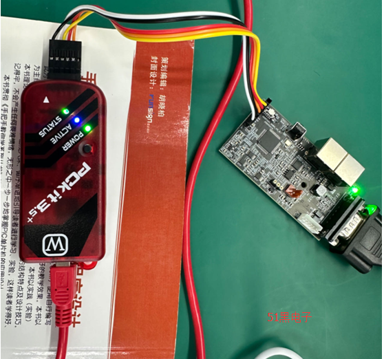
PICkit3.5通過USB接電腦,通過以下接線連接板子。
板子上的P+/P-/PGND分別接開關(guān)電源的正負(fù)15v,V+/V-/COM。
否則X IDE可能會(huì)提示以下錯(cuò)誤:
Target device was not found (could not detect target voltage VDD). You must connect to a target device to use PICkit 3.
7, 執(zhí)行mcc。
1) 在Pin Manager中,設(shè)置RD0和RB5為output。
2) 點(diǎn)擊Generate按鈕生成.c和.h文件,復(fù)制C:\Users\junha\.mcc目錄下的文件到步驟4中項(xiàng)目的目錄下,初始化入口system.c/SYSTEM_Initialize(),確保PIN_MANAGER_Initialize IO初始化正確。
TRISB = 0xFBDB;
TRISD = 0xFFFE;
8, 修改main.c,設(shè)置RED/GRN LED輸出。
void delay(int len)
{
int i = 0;
int d = 100;
i = d * len;
while(--i)
{
}
}
int main(void)
{
// initialize the device
SYSTEM_Initialize();
while (1)
{
// Add your application code
PORTB |= (1 << 5); //滅燈
PORTD &= ~(1 << 0); //點(diǎn)亮
delay(100000);
PORTB &= ~(1 << 5); //點(diǎn)亮
PORTD |= (1 << 0); //滅燈
delay(100000);
}
return 1;
}
9, 編譯:Production -> Build Main Project
10, 軟件仿真。
1) Debug Tool確保選擇Simulator。選擇這個(gè)模式后,燒錄按鈕灰掉了,不能燒錄。
2) 執(zhí)行Debug -> Debug Main Project,通過設(shè)置斷點(diǎn),watch對(duì)應(yīng)的寄存器來調(diào)試。
11, 燒錄調(diào)試
執(zhí)行Make and Program Device Main Project. 日志如下:
****************************************************
Connecting to MPLAB PICkit 3...
Currently loaded firmware on PICkit 3
Firmware Suite Version.....01.54.00
Firmware type..............dsPIC33E/24E
Target voltage detected
Target device dsPIC33EP128GS706 found.
Device Revision ID = 4002
DEVSN0 = 00000000
DEVSN1 = 00000000
Device Erased...
Programming...
The following memory area(s) will be programmed:
program memory: start address = 0x0, end address = 0x7ff
Programming/Verify complete
12, 板子自動(dòng)運(yùn)行燒錄程序,分別點(diǎn)亮RED/GRN LED。

以上圖文的Word格式文檔下載(內(nèi)容和本網(wǎng)頁上的一模一樣,方便大家保存):
 dsPIC33EP128GS706單片機(jī)調(diào)試環(huán)境搭建0515.docx
(904.82 KB, 下載次數(shù): 3)
2024-5-15 14:10 上傳
點(diǎn)擊文件名下載附件
| 