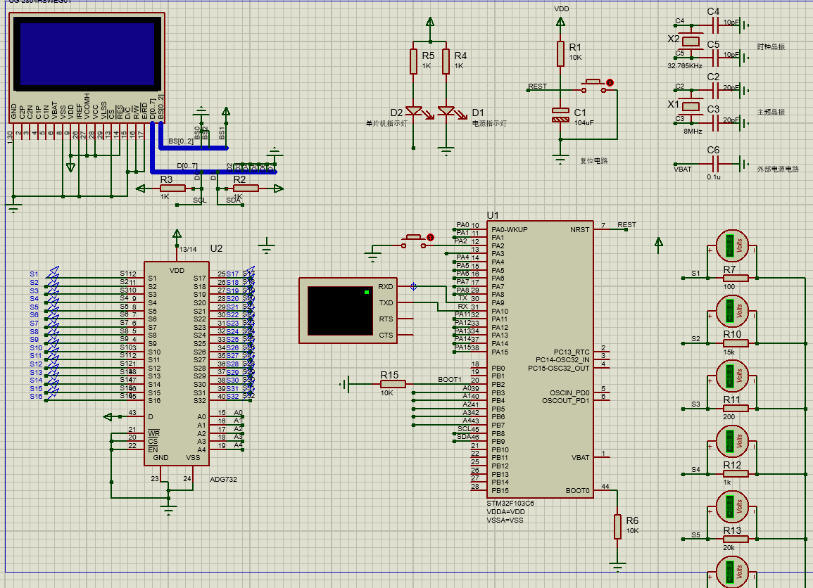
首先感謝各位大佬進來指導
本人愚鈍想使用STM32F10x單片機通過按鍵控制ADG732并完成對應開關選擇,將采集到的ADC通過串口發送到PC。
但是在操作過程中,A0-A4口一直處于低電平,不管怎么按鍵都沒有作用,想請問大家是因為我的宏定義沖突嗎亦或者其他問題,該如何修改?
另外編譯是沒有錯誤的,電路圖如圖所示
為了方便大家編譯,將部分void添加主程序

單片機源程序如下:
- #include <stm32f10x.h>
- #include <stdint.h>
- #include <stdio.h>
- #include <delay.h>
- #include <ADC.h>
- #include <Usart.h>
- #include <delay.h>
- void USART_Config(void);
- void GPIO_Config(void);
- void ADC_Config(void);
- void Switch_Pin(uint8_t pin_number, uint8_t state);
- uint16_t Read_Voltage(void);
- void Send_Voltage(uint16_t voltage);
- #define A0 PBout(3)
- #define A1 PBout(4)
- #define A2 PBout(5)
- #define A3 PBout(6)
- #define A4 PBout(7)
- #define ADC PAout(0)
- uint8_t word = 0;
- int main(void)
- {
- RCC_APB2PeriphClockCmd(RCC_APB2Periph_GPIOA | RCC_APB2Periph_GPIOB, ENABLE); // 使能GPIOA和GPIOB時鐘
- GPIO_InitTypeDef GPIO_InitStructure;
- GPIO_InitStructure.GPIO_Pin = GPIO_Pin_2;
- GPIO_InitStructure.GPIO_Mode = GPIO_Mode_IPU;
- GPIO_InitStructure.GPIO_Speed = GPIO_Speed_50MHz;
- GPIO_Init(GPIOA, &GPIO_InitStructure);
-
- RCC_APB2PeriphClockCmd(RCC_APB2Periph_GPIOB, ENABLE);
- GPIO_InitStructure.GPIO_Pin = GPIO_Pin_3 | GPIO_Pin_4 | GPIO_Pin_5 | GPIO_Pin_6 | GPIO_Pin_7;
- GPIO_InitStructure.GPIO_Mode = GPIO_Mode_Out_PP;
- GPIO_InitStructure.GPIO_Speed = GPIO_Speed_50MHz;
- GPIO_Init(GPIOB, &GPIO_InitStructure);
- delay_init();
- USART_Config();
- ADC_Config();
- uint16_t voltage;
- while(1)
- {
- if(GPIO_ReadInputDataBit(GPIOA, GPIO_Pin_2) == Bit_RESET)
- {
- // 將二進制數加1,如果達到11111則重置為00000
-
- if (word >= 32)
- {
- word = 0;
- }
- A4 = (word >> 4) & 0x01;
- A3 = (word >> 3) & 0x01;
- A2 = (word >> 2) & 0x01;
- A1 = (word >> 1) & 0x01;
- A0 = (word >> 0) & 0x01;
- delay_ms(10);
- word++;
- }
- voltage = Read_Voltage();
- Send_Voltage(voltage);
- }
- }
- //初始化串口通信
- void USART_Config(void)
- {
- // 定義串口外設結構體變量
- USART_InitTypeDef USART_InitStructure;
- // 定義GPIO外設結構體變量
- GPIO_InitTypeDef GPIO_InitStructure;
-
- // 使能USART外設的時鐘
- RCC_APB2PeriphClockCmd(RCC_APB2Periph_USART1, ENABLE);
- // 使能GPIO外設的時鐘
- RCC_APB2PeriphClockCmd(RCC_APB2Periph_GPIOA, ENABLE);
-
- // 配置GPIO外設(TX)
- GPIO_InitStructure.GPIO_Pin = GPIO_Pin_9;
- GPIO_InitStructure.GPIO_Mode = GPIO_Mode_AF_PP;
- GPIO_InitStructure.GPIO_Speed = GPIO_Speed_50MHz;
- GPIO_Init(GPIOA, &GPIO_InitStructure);
-
- // 配置GPIO外設(RX)
- GPIO_InitStructure.GPIO_Pin = GPIO_Pin_10;
- GPIO_InitStructure.GPIO_Mode = GPIO_Mode_IN_FLOATING;
- GPIO_Init(GPIOA, &GPIO_InitStructure);
-
- // 配置USART外設
- USART_InitStructure.USART_BaudRate = 115200;
- USART_InitStructure.USART_WordLength = USART_WordLength_8b;
- USART_InitStructure.USART_StopBits = USART_StopBits_1;
- USART_InitStructure.USART_Parity = USART_Parity_No;
- USART_InitStructure.USART_HardwareFlowControl = USART_HardwareFlowControl_None;
- USART_InitStructure.USART_Mode = USART_Mode_Rx | USART_Mode_Tx;
- USART_Init(USART1, &USART_InitStructure);
-
- // 使能USART外設
- USART_Cmd(USART1, ENABLE);
- }
- void GPIO_Config(void)
- {
- //使用GPIOB的引腳作為ADG732的控制端
- GPIO_InitTypeDef GPIO_InitStructure;
-
- RCC_APB2PeriphClockCmd(RCC_APB2Periph_GPIOB, ENABLE); // 使能GPIOB時鐘
- GPIO_InitStructure.GPIO_Pin = GPIO_Pin_3 | GPIO_Pin_4 | GPIO_Pin_5 | GPIO_Pin_6 | GPIO_Pin_7;
- GPIO_InitStructure.GPIO_Mode = GPIO_Mode_Out_PP;
- GPIO_InitStructure.GPIO_Speed = GPIO_Speed_50MHz;
-
- GPIO_Init(GPIOB, &GPIO_InitStructure);
- GPIO_ResetBits(GPIOB,GPIO_Pin_3); //PB.10 輸出低
- GPIO_ResetBits(GPIOB,GPIO_Pin_4);
- GPIO_ResetBits(GPIOB,GPIO_Pin_5);
- GPIO_ResetBits(GPIOB,GPIO_Pin_6); //PB.10 輸出低
- GPIO_ResetBits(GPIOB,GPIO_Pin_7);
- delay_init();
- }
- void ADC_Config(void)
- {
- ADC_InitTypeDef ADC_InitStructure;
- GPIO_InitTypeDef GPIO_InitStructure;
-
- //使能ADC和GPIO相關的時鐘
- RCC_APB2PeriphClockCmd(RCC_APB2Periph_ADC1, ENABLE);
- RCC_APB2PeriphClockCmd(RCC_APB2Periph_GPIOA, ENABLE);
-
- //配置ADC的工作模式
- ADC_InitStructure.ADC_Mode = ADC_Mode_Independent;
- ADC_InitStructure.ADC_ScanConvMode = DISABLE;
- ADC_InitStructure.ADC_ContinuousConvMode = DISABLE;
- ADC_InitStructure.ADC_ExternalTrigConv = ADC_ExternalTrigConv_None;
- ADC_InitStructure.ADC_DataAlign = ADC_DataAlign_Right;
- ADC_InitStructure.ADC_NbrOfChannel = 1;
- ADC_Init(ADC1, &ADC_InitStructure);
-
- //配置ADC的通道
- ADC_RegularChannelConfig(ADC1, ADC_Channel_0, 1, ADC_SampleTime_55Cycles5);
-
- //使能ADC
- ADC_Cmd(ADC1, ENABLE);
-
- //配置ADC的輸入GPIO
- GPIO_InitStructure.GPIO_Pin = GPIO_Pin_3;
- GPIO_InitStructure.GPIO_Mode = GPIO_Mode_AIN;
- GPIO_Init(GPIOA, &GPIO_InitStructure);
-
- //復位ADC校準寄存器
- ADC_ResetCalibration(ADC1);
-
- //等待校準寄存器復位完成
- while(ADC_GetResetCalibrationStatus(ADC1));
-
- //開始校準ADC
- ADC_StartCalibration(ADC1);
-
- //等待校準完
- }
- void Switch_Pin(uint8_t pin_number, uint8_t state)
- {
- //首先,需要對選擇的引腳進行初始化,以便進行輸出
- GPIO_InitTypeDef GPIO_InitStructure;
- GPIO_InitStructure.GPIO_Pin = GPIO_Pin_2;
- GPIO_InitStructure.GPIO_Mode = GPIO_Mode_Out_PP;
- GPIO_InitStructure.GPIO_Speed = GPIO_Speed_50MHz;
- GPIO_Init(GPIOA, &GPIO_InitStructure);
- //將引腳狀態設置為指定的狀態(0或1)
- if(state == 0)
- GPIO_ResetBits(GPIOA, GPIO_Pin_2);
- else
- GPIO_SetBits(GPIOA, GPIO_Pin_2);
- }
- // 讀取電壓值函數
- uint16_t Read_Voltage(void)
- {
- // 啟動ADC轉換
- ADC_SoftwareStartConvCmd(ADC1, ENABLE);
- // 等待轉換完成
- while(!ADC_GetFlagStatus(ADC1, ADC_FLAG_EOC));
- // 讀取轉換結果
- uint16_t adc_value = ADC_GetConversionValue(ADC1);
- // 計算電壓值
- float voltage = (float)adc_value / 4096 * 3.3;
- uint16_t voltage_mv = (uint16_t)(voltage * 1000);
- return voltage_mv;
- }
- void Send_Voltage(uint16_t voltage)
- {
- char buffer[16];
- sprintf(buffer, "%d\r\n", voltage);
- for(int i = 0; buffer[i] != '\0'; i++)
- {
- USART_SendData(USART1, buffer[i]);
- while(USART_GetFlagStatus(USART1, USART_FLAG_TXE) == RESET);
- }
- }
|