1 介紹
自己在研究一個題目,就是如何把MPU6050輸出的加速度和角速度換算成角度。所以我想在市面上找一個MPU6050,可以自己輸出的角度的,這樣我就能做一個對比了。同時,能夠把IIC引腳留出來的方便我自己開發MPU6050芯片。我在淘寶上找到了一款JY61模塊。它內置的是MPU6050芯片。串口直接輸出的很簡單。給大家看下圖片:
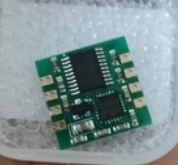
JY61
2 MPU6050的工作過程
MPU6050 IMU在單芯片上集成了一個3軸加速度計和一個3軸陀螺儀。陀螺儀沿X、Y和Z軸測量角位置隨時間的旋轉速度或變化率。它使用MEMS技術和科里奧利效應進行測量。陀螺儀的輸出以每秒度數為單位,因此為了獲得角度位置,我們只需要對角速度進行積分。另一方面,MPU6050加速度計測量加速度的方式與ADXL345加速度傳感器相同。簡而言之,它可以測量沿3個軸的重力加速度,并使用一些三角學數學,我們可以計算傳感器定位的角度。因此,如果我們融合或組合加速度計和陀螺儀數據,我們可以獲得有關傳感器方向的非常準確的信息。MPU6050 IMU也稱為六軸運動跟蹤設備或6 DoF(六自由度)設備,因為它有6個輸出,即3個加速度計輸出和3個陀螺儀輸出。
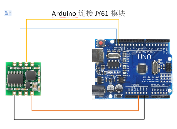
3 Arduino和MPU6050的連接方法
我們來看看如何使用Arduino連接和讀取MPU6050傳感器的數據。我們使用I2C協議與Arduino進行通信,因此只需要兩條線進行連接,另外還有兩條線用于供電。
4 MPU6050的Arduino代碼
以下是用于從MPU6050傳感器讀取數據的Arduino代碼。這個代碼可以直接復制使用的。在代碼下方,您可以找到它的詳細說明。
*
Arduino and MPU6050 Accelerometer and Gyroscope Sensor Tutorial
*/
#include <Wire.h>
const int MPU = 0x68; // MPU6050 I2C address
float AccX, AccY, AccZ;
float GyroX, GyroY, GyroZ;
float accAngleX, accAngleY, gyroAngleX, gyroAngleY, gyroAngleZ;
float roll, pitch, yaw;
float AccErrorX, AccErrorY, GyroErrorX, GyroErrorY, GyroErrorZ;
float elapsedTime, currentTime, previousTime;
int c = 0;
void setup() {
Serial.begin(19200);
Wire.begin(); // Initialize comunication
Wire.beginTransmission(MPU); // Start communication with MPU6050 // MPU=0x68
Wire.write(0x6B); // Talk to the register 6B
Wire.write(0x00); // Make reset - place a 0 into the 6B register
Wire.endTransmission(true); //end the transmission
/*
// Configure Accelerometer Sensitivity - Full Scale Range (default +/- 2g)
Wire.beginTransmission(MPU);
Wire.write(0x1C); //Talk to the ACCEL_CONFIG register (1C hex)
Wire.write(0x10); //Set the register bits as 00010000 (+/- 8g full scale range)
Wire.endTransmission(true);
// Configure Gyro Sensitivity - Full Scale Range (default +/- 250deg/s)
Wire.beginTransmission(MPU);
Wire.write(0x1B); // Talk to the GYRO_CONFIG register (1B hex)
Wire.write(0x10); // Set the register bits as 00010000 (1000deg/s full scale)
Wire.endTransmission(true);
delay(20);
*/
// Call this function if you need to get the IMU error values for your module
calculate_IMU_error();
delay(20);
}
void loop() {
// === Read acceleromter data === //
Wire.beginTransmission(MPU);
Wire.write(0x3B); // Start with register 0x3B (ACCEL_XOUT_H)
Wire.endTransmission(false);
Wire.requestFrom(MPU, 6, true); // Read 6 registers total, each axis value is stored in 2 registers
//For a range of +-2g, we need to divide the raw values by 16384, according to the datasheet
AccX = (Wire.read() << 8 | Wire.read()) / 16384.0; // X-axis value
AccY = (Wire.read() << 8 | Wire.read()) / 16384.0; // Y-axis value
AccZ = (Wire.read() << 8 | Wire.read()) / 16384.0; // Z-axis value
// Calculating Roll and Pitch from the accelerometer data
accAngleX = (atan(AccY / sqrt(pow(AccX, 2) + pow(AccZ, 2))) * 180 / PI) - 0.58; // AccErrorX ~(0.58) See the calculate_IMU_error()custom function for more details
accAngleY = (atan(-1 * AccX / sqrt(pow(AccY, 2) + pow(AccZ, 2))) * 180 / PI) + 1.58; // AccErrorY ~(-1.58)
// === Read gyroscope data === //
previousTime = currentTime; // Previous time is stored before the actual time read
currentTime = millis(); // Current time actual time read
elapsedTime = (currentTime - previousTime) / 1000; // Divide by 1000 to get seconds
Wire.beginTransmission(MPU);
Wire.write(0x43); // Gyro data first register address 0x43
Wire.endTransmission(false);
Wire.requestFrom(MPU, 6, true); // Read 4 registers total, each axis value is stored in 2 registers
GyroX = (Wire.read() << 8 | Wire.read()) / 131.0; // For a 250deg/s range we have to divide first the raw value by 131.0, according to the datasheet
GyroY = (Wire.read() << 8 | Wire.read()) / 131.0;
GyroZ = (Wire.read() << 8 | Wire.read()) / 131.0;
// Correct the outputs with the calculated error values
GyroX = GyroX + 0.56; // GyroErrorX ~(-0.56)
GyroY = GyroY - 2; // GyroErrorY ~(2)
GyroZ = GyroZ + 0.79; // GyroErrorZ ~ (-0.8)
// Currently the raw values are in degrees per seconds, deg/s, so we need to multiply by sendonds (s) to get the angle in degrees
gyroAngleX = gyroAngleX + GyroX * elapsedTime; // deg/s * s = deg
gyroAngleY = gyroAngleY + GyroY * elapsedTime;
yaw = yaw + GyroZ * elapsedTime;
// Complementary filter - combine acceleromter and gyro angle values
roll = 0.96 * gyroAngleX + 0.04 * accAngleX;
pitch = 0.96 * gyroAngleY + 0.04 * accAngleY;
// Print the values on the serial monitor
Serial.print(roll);
Serial.print("/");
Serial.print(pitch);
Serial.print("/");
Serial.println(yaw);
}
void calculate_IMU_error() {
// We can call this funtion in the setup section to calculate the accelerometer and gyro data error. From here we will get the error values used in the above equations printed on the Serial Monitor.
// Note that we should place the IMU flat in order to get the proper values, so that we then can the correct values
// Read accelerometer values 200 times
while (c < 200) {
Wire.beginTransmission(MPU);
Wire.write(0x3B);
Wire.endTransmission(false);
Wire.requestFrom(MPU, 6, true);
AccX = (Wire.read() << 8 | Wire.read()) / 16384.0 ;
AccY = (Wire.read() << 8 | Wire.read()) / 16384.0 ;
AccZ = (Wire.read() << 8 | Wire.read()) / 16384.0 ;
// Sum all readings
AccErrorX = AccErrorX + ((atan((AccY) / sqrt(pow((AccX), 2) + pow((AccZ), 2))) * 180 / PI));
AccErrorY = AccErrorY + ((atan(-1 * (AccX) / sqrt(pow((AccY), 2) + pow((AccZ), 2))) * 180 / PI));
c++;
}
//Divide the sum by 200 to get the error value
AccErrorX = AccErrorX / 200;
AccErrorY = AccErrorY / 200;
c = 0;
// Read gyro values 200 times
while (c < 200) {
Wire.beginTransmission(MPU);
Wire.write(0x43);
Wire.endTransmission(false);
Wire.requestFrom(MPU, 6, true);
GyroX = Wire.read() << 8 | Wire.read();
GyroY = Wire.read() << 8 | Wire.read();
GyroZ = Wire.read() << 8 | Wire.read();
// Sum all readings
GyroErrorX = GyroErrorX + (GyroX / 131.0);
GyroErrorY = GyroErrorY + (GyroY / 131.0);
GyroErrorZ = GyroErrorZ + (GyroZ / 131.0);
c++;
}
//Divide the sum by 200 to get the error value
GyroErrorX = GyroErrorX / 200;
GyroErrorY = GyroErrorY / 200;
GyroErrorZ = GyroErrorZ / 200;
// Print the error values on the Serial Monitor
Serial.print("AccErrorX: ");
Serial.println(AccErrorX);
Serial.print("AccErrorY: ");
Serial.println(AccErrorY);
Serial.print("GyroErrorX: ");
Serial.println(GyroErrorX);
Serial.print("GyroErrorY: ");
Serial.println(GyroErrorY);
Serial.print("GyroErrorZ: ");
Serial.println(GyroErrorZ);
}
代碼描述:首先我們需要包含用于I2C通信的Wire.h庫,并定義一些存儲數據所需的變量。
在setup()函數部分,我們需要初始化wire庫并通過電源管理寄存器復位傳感器。 為此,我們需要查看傳感器的數據手冊,從中我們可以看到寄存器地址。
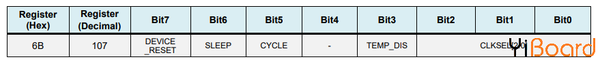
MPU6050電源管理寄存器0x6B
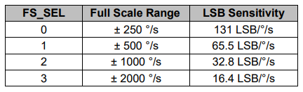
此外,如果需要,我們可以使用配置寄存器為加速度計和陀螺儀選擇滿量程范圍。 對于這個例子,我們將使用加速度計的默認±2g范圍和陀螺儀的250度/秒范圍。
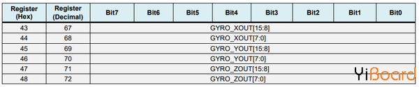
在loop()函數部分,我們首先讀取加速度計的數據。 每個軸的數據存儲在兩個字節或寄存器中,我們可以從傳感器的數據手冊中看到這些寄存器的地址。
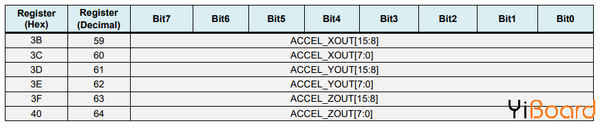
MPU6050 imu加速度計數據寄存器
為了全部讀取它們,我們從第一個寄存器開始,然后使用requiestFrom()函數,我們請求讀取X、Y和Z軸的所有6個寄存器。 然后我們從每個寄存器讀取數據,并且由于輸出是二進制補碼,我們將它們相應地組合以獲得正確的值。
[backcolor=inherit !important]
為了獲得-1g到+ 1g的輸出值,適合計算角度,我們將輸出除以先前選擇的靈敏度。
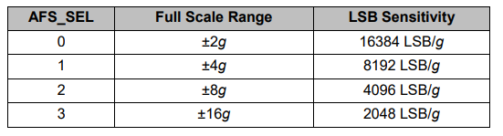
mpu6050加速度計靈敏度滿量程范圍
最后,使用這兩個公式,我們從加速度計數據計算滾轉角和俯仰角。
[backcolor=inherit !important]
接下來,使用相同的方法我們得到陀螺儀數據。
我們讀取了六個陀螺儀寄存器,適當地組合它們的數據并將其除以先前選擇的靈敏度,以便以每秒的度數獲得輸出。
[backcolor=inherit !important]
在這里你可以注意到我用一些小的計算誤差值來校正輸出值,我將在接下來解釋它們是如何得到它們的。 因此,當輸出以度/秒為單位時,現在我們需要將它們與時間相乘以得到度數。 使用millis()函數在每次讀取迭代之前捕獲時間值。
[backcolor=inherit !important]
最后,我們使用互補濾波器融合加速度計和陀螺儀數據。在這里,我們采用96%的陀螺儀數據,因為它非常準確,不會受到外力的影響。陀螺儀的缺點是存在漂移,或者隨著時間的推移在輸出中引入誤差。因此,從長遠來看,我們使用來自加速度計的數據,本例為4%,足以消除陀螺儀的漂移誤差。
[backcolor=inherit !important]
但是,由于我們無法從加速度計數據計算偏航,我們無法在其上實現互補濾波器。
在我們看一下結果之前,讓我快速解釋一下如何獲得糾錯值。為了計算這些錯誤,我們可以在傳感器處于平坦靜止位置時調用calculate_IMU_error()自定義函數。在這里,我們為所有輸出做了200個讀數,我們將它們相加并將它們除以200。由于我們將傳感器保持在平坦靜止位置,因此預期輸出值應為0。因此,通過此計算,我們可以得到傳感器的平均誤差。
[backcolor=inherit !important]
輸出結果
我們只需在串行監視器上打印這些值,一旦我們知道它們,我們就可以在前面所示的代碼中實現它們,用于滾動和俯仰計算,以及3個陀螺儀輸出。
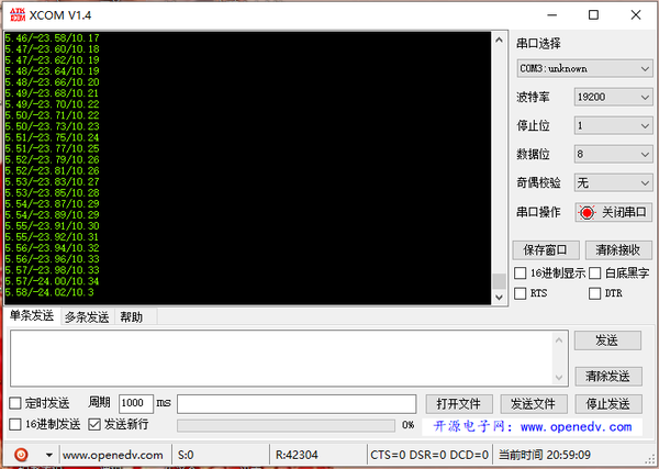
最后,使用Serial.print函數,我們可以在串行監視器上打印Roll、Pitch和Yaw值,看看傳感器是否正常工作。
|


 QQ好友和群
 QQ空間
QQ空間 騰訊微博
騰訊微博 騰訊朋友
騰訊朋友 收藏
收藏 淘帖
淘帖 頂
頂 踩
踩

