原理圖鏈接

VHDL硬件描述語言是一門技術性、應用性很強的學科,學生不但能夠將課堂上學到的理論知識與實際應用結合起來,而且能夠對分析、解決實際問題的數字電路問題進一步加深認識,為今后能夠獨立進行某些數字應用系統的開發設計工作打下一定的基礎。本次的設計是基于VHDL的實時時鐘電路設計,完成時、分、秒的顯示及調整設置功能。設計利用VHDL語言自頂向下的設計理念,突出其作為硬件描述語言的良好的可讀性、可移植性以及易于理解等優點。通過QuartusII5.1和QuartusII12.1軟件完成仿真、綜合。程序下載到FPGA芯片后,可用于實際的數字鐘顯示。
2. 主要問題
進行實驗的過程中有許多的問題,一開始不知道原理,對程序無從下手;編寫過程中有語和定義錯誤,在模塊調用時出現重復;不知道如何分配管腳以致調試錯誤。在分頻模塊的順序添加上,在計時模塊的小時分鐘調節上,數碼管的譯碼也遇到了問題。
3. 解決方法
在向老師和同學請教,查詢相關資料以及網上查找以后,上述問題得以解決。
4. 最終結果
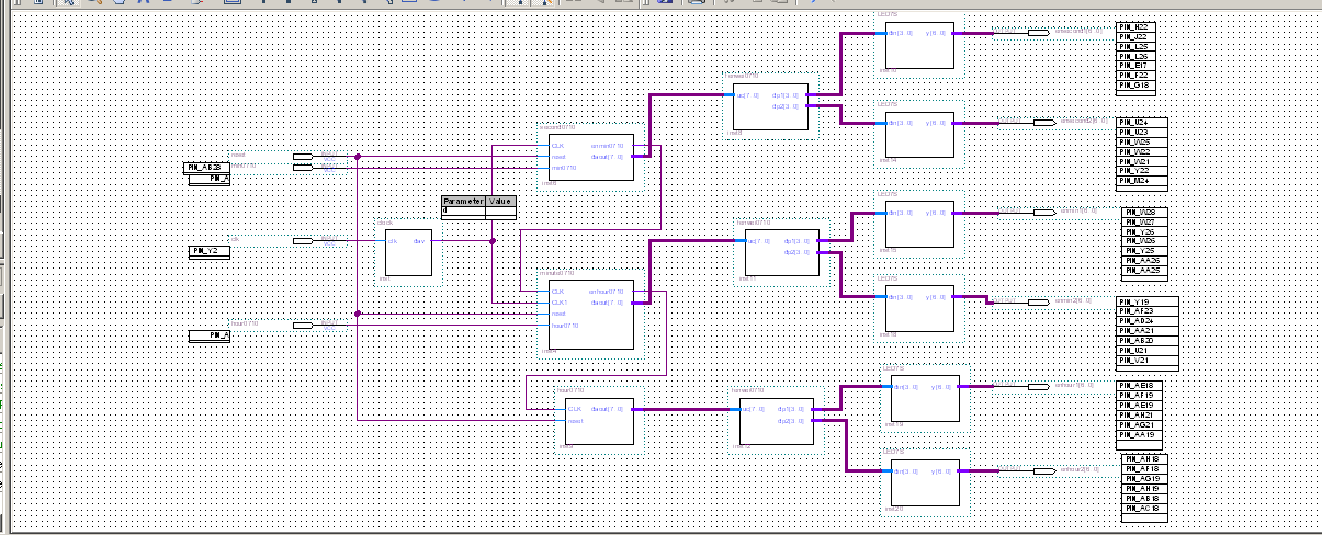
此次設計的邏輯結構主要由分頻、計數和譯碼顯示三個模塊構成。分頻模塊將50MHz系統基準時鐘分頻產生時鐘信號,由輸入端控制輸出時鐘信號,有正常的計數功能。數字時鐘計時工作模塊,計時模塊對1Hz的時鐘信號進行計時,分為時、分、秒三個部分;最后通過主模塊調用三個子模塊函數實現整體設計要求。
實時時鐘電路設計:
(1) 設計一個數碼管實時顯示時、分、秒的數字時鐘(24小時顯示模式);
(2) 為了演示方便,應具有分鐘、小時快進功能;
(3) 時、分、秒的設置功能(選作)。
2 方案分析與總體設計
本次的設計是基于VHDL的實時時鐘電路設計,完成時、分、秒的顯示及調整功能。此次設計的邏輯結構主要由分頻、計數、譯碼三個模塊構成。分頻模塊將50MHz系統基準時鐘分頻產生兩路時鐘信號,一路是1Hz的數字鐘計時工作頻率,一路是數碼管動態顯示的掃描頻率;計時模塊對1Hz的時鐘信號進行計時,分為時、分、秒三個部分,同時具有時分秒調整功能,方便演示;譯碼顯示模塊采用動態掃描的方式完成8個7位數碼管的動態顯示,最后通過主模塊調用三個子模塊實現整體設計要求。
綜上,給出如下輸入輸出變量:
輸入變量:1.時鐘信號: 每個時鐘的上升沿觸發系統的狀態轉換;
2.計時復位信號:下降沿觸發,按下后計時自動回到初始狀態;
3.使能信號:激發時鐘工作。
輸出變量:1.數碼管信號:按位輸入到數碼管,顯示時鐘;
2.計時時鐘信號:分頻后的計時時鐘信號;
3.進位信號:進制轉換。
3 各功能模塊原理及實現
3.1 功能模塊設計3.1.1 分頻模塊
1. 設計原理
本時鐘電路的設計中使用DE2-115時鐘芯片,故需對系統提供的50MHz時鐘頻率進行分頻,得到計時所需的時鐘頻率。
定義變量并根據需要得到的分頻信號設定計數值,對該變量進行加或減計數,每到達一次計數值點,將該變量清零或重置,并且對輸出信號取一次反,即可以得到所需的分頻信號。本模塊采用此方法實現上述所需時鐘信號的分頻功能。
代碼實現
library ieee;
use ieee.STD_logic_1164.all;
use ieee.STD_logic_unsigned.all;
entity clock0710 is -- divide50MHz to 1Hz
generic(d : integer :=50000000);
port( clk: in STD_logic;
dav: out STD_logic);
end;
architecture bhv of clock0710 is
signal s : STD_logic;
signal c :STD_logic_vector(25 downto 0);
begin
process(clk)
--variable cnt:STD_logic_vector(25 downto 0);
begin
if clk'event and clk='1'then
if c = (d-1) then
c <="00000000000000000000000000";s <= '1';
elsif c >= d/2then
c <= c+ 1;s <= '1';
else c <= c +1;s <= '0';
end if;
end if;
end process;
dav <= s;
end;
3.1.2計數模塊
1. 設計原理
計數模塊采用對1秒的信號源進行計數并向高位進位的思想實現計時功能,采用6個變量分別對時分秒的高低位進行計數,低位滿后向高位進位。
2. 代碼實現
時鐘
library ieee;
useieee.std_logic_1164.all;
useieee.std_logic_unsigned.all;
entity hour0710 is
port(CLK,reset:instd_logic;
daout:out std_logic_vector(7 downto 0));
end entity hour0710;
architecture fun ofhour0710 is signal count:std_logic_vector(7 downto 0);
begin
daout<=count;
process(CLK,reset)
begin
IF(reset='0')THENcount<="00000000"; --若reset=0,則異步清零
elsif(CLK'event andCLK='1')then --否則,若clk上升沿到
if(count(3 downto0)="1001")then --若個位計時恰好到"1001"即9
if(count<16#23#)then --23進制
count<=count+7; --若到23D則
else
count<="00000000"; --復0
end if;
elsif(count<16#23#)then --若未到23D,則count進1
count<=count+1;
else --否則清零
count<="00000000";
end if; --end if(count(3downto 0)="1001")
end if; --end if(reset='0')
end process;
end fun;
分鐘
library ieee;
use ieee.std_logic_1164.all;
useieee.std_logic_unsigned.all;
entity minute0710 is
port(CLK,CLK1,reset,hour0710:instd_logic;
enhour0710:out std_logic;
daout:out std_logic_vector(7 downto 0));
end entity minute0710;
architecture fun ofminute0710 is
signal count:std_logic_vector(7downto 0);
signalenhour0710_1,enhour0710_2:std_logic;--enhour0710_1為59分時的進位信號
begin --enhour0710_2由clk調制后的手動調時脈沖信號串
daout<=count;
enhour0710_2<=(hour0710and CLK1); --enhour0710為手動調時控制信號,高電平有效
enhour0710<=(enhour0710_1or enhour0710_2);
process(CLK,reset,hour0710)
begin
if(reset='0')thencount<="00000000"; --若reset=0,則異步清零
elsif(CLK'event andCLK='1')then --否則,若clk上升沿到
if(count(3 downto0)="1001")then --若個位計時恰好到"1001"即9
if(count<16#60#)then --又若count小于 16#60#,即60
if(count="1011001")then --又若59D
enhour0710_1<='1'; --則置進位為1
count<="00000000"; --count復0
else
count<=count+7; --若count未到59D,則加7,即作"加6校正"
end if; --使前面的16#60#的個位轉變為8421BCD的容量
elsecount<="00000000"; --count復0(有此句,則對無效狀態電路可自啟動)
end if; --end if(count<16#60#)
elsif(count<16#60#)then
count<=count+1; --若count<16#60#,則count加1
enhour0710_1<='0'after100 ns; --沒有發生進位
elsecount<="00000000"; --否則,若count不小于16#60#,count復0
end if; --endif(count(3 downto 0)="1001")
end if; --endif(reset='0')
end process;
end fun;
秒鐘
library ieee;
useieee.std_logic_1164.all;
useieee.std_logic_unsigned.all;
entity second0710 is
port(CLK,reset,min0710:std_logic;
enmin0710:out std_logic;
daout:out std_logic_vector(7 downto 0));
end entity second0710;
architecture fun ofsecond0710 is signal count:std_logic_vector(7 downto 0);
signal
enmin0710_1,enmin0710_2:std_logic;--enmin0710_1為59分時的進位信號
begin --enmi0710_2由clk調制后的手動調時脈沖信號串
daout<=count;
enmin0710_2<=(min0710and CLK); --enmin0710為手動調時控制信號,高電平有效
enmin0710<=(enmin0710_1or enmin0710_2);--enmin為向分進位信號
process(CLK,reset,min0710)
begin
if(reset='0')thencount<="00000000";--若reset=0,則異步清零
elsif(CLK'event andCLK='1')then --否則,若clk上升沿到
if(count(3 downto0)="1001")then --若個位計時恰好到"1001"即9
if(count<16#60#)then --又若count小于 16#60#,即60H
if(count="1011001")then --又若59D
enmin0710_1<='1';count<="00000000";--則置進位為1 count復0
else --未到59D
count<=count+7; --則加7,而+7=+1+6,即作"加6校正"
end if;
else --若count不小于16#60#
count<="00000000"; --count復0
end if; --end
elsif(count<16#60#)then --若個位計時未到"1001"則轉此句再判
count<=count+1; --若count<16#60#,則count加1
enmin0710_1<='0'after100 ns; --沒有發生進位
else --否則,若count不小于16#60#
count<="00000000"; --count復0
end if; --end if(count(3downto 0)="1001")
end if; --endif(reset='0')
end process;
end fun;
3.1.3 數碼管顯示模塊
1. 設計原理
譯碼顯示模塊是將時間的數值轉化成數碼管段碼值,計數器將分頻器分頻的信號計數后傳給了譯碼器翻譯成7位的信號傳給晶體管。選六個晶體管來分別記錄時分秒,分為兩組數碼管,所以分別定義高位和低位和來分別控制兩組數碼管。
2. 代碼實現
分位
library ieee;
use ieee.std_logic_1164.all;
use ieee.std_logic_unsigned.all;
entity fenwei0710 is
port(uc:in std_logic_vector(7 downto 0);
dp1,dp2:out std_logic_vector(3 downto 0));
end;
architecture ott of fenwei0710 is
begin
process(uc)
begin
dp1(3 downto 0)<=uc(3 downto 0);
dp2(3 downto 0)<=uc(7 downto 4);
end process;
end;
譯碼器
library ieee;
use ieee.std_logic_1164.all;
use ieee.std_logic_unsigned.all;
entity LED7S is
Port(din: in std_logic_vector(3 downto 0);
y: out std_logic_vector(6 downto 0));
end LED7S;
architecture one of LED7S is
begin
process(din)
begin
case dinis
when "0000" =>y<="1000000"; ---Display "0"
when "0001" =>y<="1111001"; ---Display "1"
when "0010" =>y<="0100100"; ---Display "2"
when "0011" =>y<="0110000"; ---Display "3"
when "0100" =>y<="0011001"; ---Display "4"
when "0101" =>y<="0010010"; ---Display "5"
when "0110" =>y<="0000010"; ---Display "6"
when "0111" =>y<="1111000"; ---Display "7"
when "1000" =>y<="0000000"; ---Display "8"
when "1001" =>y<="0010000"; ---Display "9"
when "1010" =>y<="0001000"; ---Display "A"
when "1011" => y<="0000011"; --- Display "B"
when "1100" =>y<="1000110"; ---Display "C"
when "1101" =>y<="0100001"; ---Display "D"
when "1110" =>y<="0000110"; ---Display "E"
when "1111" =>y<="0001110"; ---Display "F"
when others => y<=null;
end case;
end process;
end one;
3.2 整體功能測試
整體頂層模塊程序代碼及原理圖
-- Copyright (C)1991-2006 Altera Corporation
-- Your use ofAltera Corporation's design tools, logic functions
-- and othersoftware and tools, and its AMPP partner logic
-- functions, andany output files any of the foregoing
-- (includingdevice programming or simulation files), and any
-- associateddocumentation or information are expressly subject
-- to the termsand conditions of the Altera Program License
-- SubscriptionAgreement, Altera MegaCore Function License
-- Agreement, orother applicable license agreement, including,
-- withoutlimitation, that your use is for the sole purpose of
-- programminglogic devices manufactured by Altera and sold by
-- Altera or itsauthorized distributors. Please refer tothe
-- applicableagreement for further details.
-- PROGRAM"Quartus II"
-- VERSION"Version 5.1 Build 216 03/06/2006 Service Pack 2 SJ Full Version"
LIBRARY ieee;
USEieee.std_logic_1164.all;
LIBRARY work;
ENTITY Block1 IS
port
(
reset : IN STD_LOGIC;
min0710 : IN STD_LOGIC;
clk : IN STD_LOGIC;
hour0710 : IN STD_LOGIC;
enhour1 : OUT STD_LOGIC_VECTOR(6 downto 0);
enhour2 : OUT STD_LOGIC_VECTOR(6 downto 0);
enmin1 : OUT STD_LOGIC_VECTOR(6 downto 0);
enmin2 : OUT STD_LOGIC_VECTOR(6 downto 0);
ensecond1 : OUT STD_LOGIC_VECTOR(6 downto 0);
ensecond2 : OUT STD_LOGIC_VECTOR(6 downto 0)
);
END Block1;
ARCHITECTUREbdf_type OF Block1 IS
component clock
GENERIC ();
PORT(clk : IN STD_LOGIC;
dav : OUT STD_LOGIC
);
end component;
component led7s
PORT(din : IN STD_LOGIC_VECTOR(3 downto0);
y : OUT STD_LOGIC_VECTOR(6 downto 0)
);
end component;
componentfenwei0710
PORT(uc : IN STD_LOGIC_VECTOR(7 downto0);
dp1 : OUT STD_LOGIC_VECTOR(3 downto 0);
dp2 : OUT STD_LOGIC_VECTOR(3 downto 0)
);
end component;
componentminute0710
PORT(CLK : IN STD_LOGIC;
CLK1 : IN STD_LOGIC;
reset : IN STD_LOGIC;
hour0710 : IN STD_LOGIC;
enhour0710 : OUT STD_LOGIC;
daout : OUT STD_LOGIC_VECTOR(7 downto 0)
);
end component;
componentsecond0710
PORT(CLK : IN STD_LOGIC;
reset : IN STD_LOGIC;
min0710 : IN STD_LOGIC;
enmin0710 : OUT STD_LOGIC;
daout : OUT STD_LOGIC_VECTOR(7 downto 0)
);
end component;
component hour0710
PORT(CLK : IN STD_LOGIC;
reset : IN STD_LOGIC;
daout : OUT STD_LOGIC_VECTOR(7 downto 0)
);
end component;
signal SYNTHESIZED_WIRE_0 : STD_LOGIC_VECTOR(3 downto 0);
signal SYNTHESIZED_WIRE_1 : STD_LOGIC_VECTOR(7 downto 0);
signal SYNTHESIZED_WIRE_2 : STD_LOGIC_VECTOR(7 downto 0);
signal SYNTHESIZED_WIRE_3 : STD_LOGIC_VECTOR(3 downto 0);
signal SYNTHESIZED_WIRE_4 : STD_LOGIC_VECTOR(3 downto 0);
signal SYNTHESIZED_WIRE_5 : STD_LOGIC_VECTOR(3 downto 0);
signal SYNTHESIZED_WIRE_6 : STD_LOGIC_VECTOR(3 downto 0);
signal SYNTHESIZED_WIRE_7 : STD_LOGIC_VECTOR(3 downto 0);
signal SYNTHESIZED_WIRE_8 : STD_LOGIC;
signal SYNTHESIZED_WIRE_13 : STD_LOGIC;
signal SYNTHESIZED_WIRE_11 : STD_LOGIC_VECTOR(7 downto 0);
signal SYNTHESIZED_WIRE_12 : STD_LOGIC;
BEGIN
b2v_inst : clock
GENERIC MAP()
PORT MAP(clk =>clk,
dav => SYNTHESIZED_WIRE_13);
b2v_inst10 : led7s
PORT MAP(din =>SYNTHESIZED_WIRE_0,
y => ensecond1);
b2v_inst11 :fenwei0710
PORT MAP(uc =>SYNTHESIZED_WIRE_1,
dp1 => SYNTHESIZED_WIRE_4,
dp2 => SYNTHESIZED_WIRE_5);
b2v_inst12 :fenwei0710
PORT MAP(uc =>SYNTHESIZED_WIRE_2,
dp1 => SYNTHESIZED_WIRE_6,
dp2 => SYNTHESIZED_WIRE_7);
b2v_inst14 : led7s
PORT MAP(din =>SYNTHESIZED_WIRE_3,
y => ensecond2);
b2v_inst15 : led7s
PORT MAP(din =>SYNTHESIZED_WIRE_4,
y => enmin1);
b2v_inst18 : led7s
PORT MAP(din =>SYNTHESIZED_WIRE_5,
y => enmin2);
b2v_inst19 : led7s
PORT MAP(din =>SYNTHESIZED_WIRE_6,
y => enhour1);
b2v_inst20 : led7s
PORT MAP(din =>SYNTHESIZED_WIRE_7,
y => enhour2);
b2v_inst4 :minute0710
PORT MAP(CLK =>SYNTHESIZED_WIRE_8,
CLK1 => SYNTHESIZED_WIRE_13,
reset => reset,
hour0710 => hour0710,
enhour0710 => SYNTHESIZED_WIRE_12,
daout => SYNTHESIZED_WIRE_1);
b2v_inst6 :second0710
PORT MAP(CLK =>SYNTHESIZED_WIRE_13,
reset => reset,
min0710 => min0710,
enmin0710 => SYNTHESIZED_WIRE_8,
daout => SYNTHESIZED_WIRE_11);
b2v_inst8 :fenwei0710
PORT MAP(uc =>SYNTHESIZED_WIRE_11,
dp1 => SYNTHESIZED_WIRE_0,
dp2 => SYNTHESIZED_WIRE_3);
b2v_inst9 :hour0710
PORT MAP(CLK =>SYNTHESIZED_WIRE_12,
reset => reset,
daout => SYNTHESIZED_WIRE_2);
END;
實驗箱調試結果
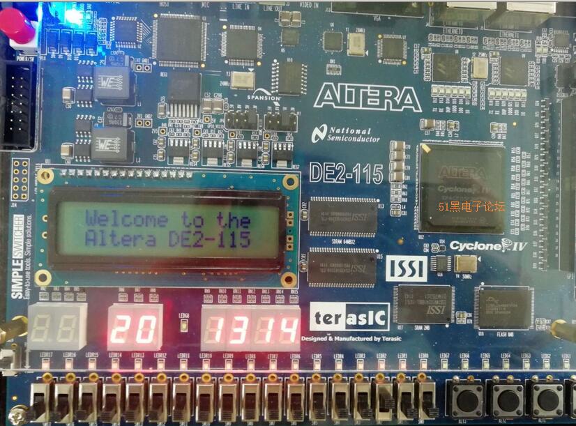
將程序下載到實驗箱上,撥動開關SW2小時自動調節,撥動開關SW1分鐘自動調節,按下開關SW0,所有時間會自動清零。
|