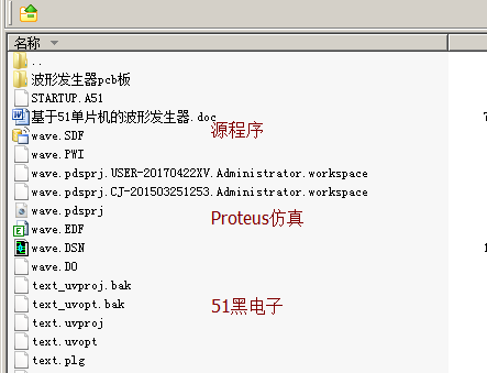
基于51單片機的波形發生器,里面包含了仿真文件和源程序,pcb文件。
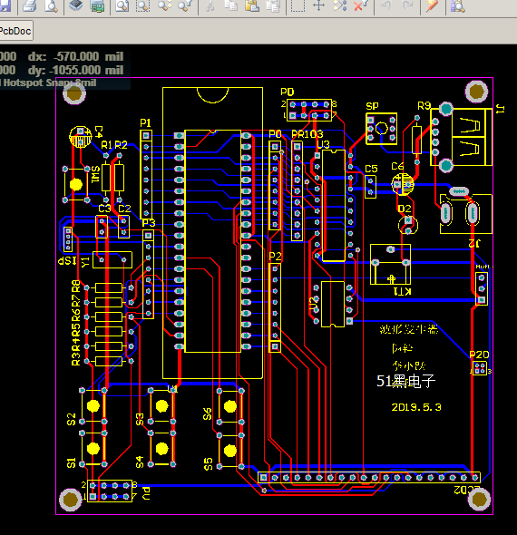
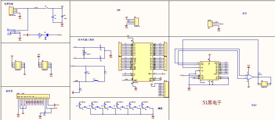
Altium Designer畫的波形發生器原理圖和PCB圖如下:(51hei附件中可下載工程文件)


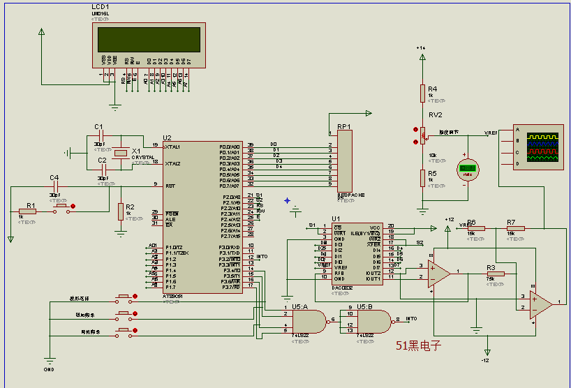
仿真原理圖如下(proteus仿真工程文件可到本帖附件中下載)

單片機源程序如下:
- #include<reg52.h>
- #define uchar unsigned char
- #define uint unsigned int
- #define DAdata P0 //DA數據端口
- sbit DA_S1= P2^0; // 控制DAC0832的8位輸入寄存器,僅當都為0時,可以輸出數據(處于直通狀態),否則,輸出將被鎖存
- sbit DA_S2= P2^1; // 控制DAC0832的8位DAC寄存器,僅當都為0時,可以輸出數據(處于直通狀態),否則,輸出將被鎖存
- sbit key= P3^2;
- uchar wavecount; //'抽點'計數
- uchar THtemp,TLtemp;//傳遞頻率的中間變量
- uchar judge=1; //在方波輸出函數中用于簡單判別作用
- uchar waveform; //當其為0、1、2時,分別代表三種波
- uchar code freq_unit[3]={10,50,200}; //三種波的頻率單位
- uchar idata wavefreq[3]={1,1,1}; //給每種波定義一個數組單元,用于存放單位頻率的個數
- uchar code lcd_hang1[]={"Sine Wave " "Triangle Wave " "Square Wave " "Select Wave: " "press No.1 key! "};
- uchar idata lcd_hang2[16]={"f= Hz "};
- uchar code waveTH[]={
- 0xfd,0xfe,0xff,0xff,0xff,0xff,0xff,0xff,0xff,0xff,
- 0xfd,0xfe,0xff,0xff,0xff,0xff,0xff,0xff,0xff,0xff,
- 0xec,0xf6,0xf9,0xfb,0xfc,0xfc,0xfd,0xfd,0xfd,0xfe};
- uchar code waveTL[]={
- 0x06,0x8a,0x10,0x4e,0x78,0x93,0xa8,0xb3,0xbe,0xc6, //正弦波頻率調整中間值
- 0xac,0xde,0x48,0x7a,0x99,0xaf,0xbb,0xc8,0xd0,0xde, //三角波頻率調整中間值
- 0x88,0x50,0x90,0x32,0x34,0xbe,0x4a,0xa3,0xe5,0x2c};
- /*************************************************************************************************/
- uchar code triangle_tab[]={ //每隔數字8,采取一次
- 0x00,0x08,0x10,0x18,0x20,0x28,0x30,0x38,0x40,0x48,0x50,0x58,0x60,0x68,0x70,0x78,
- 0x80,0x88,0x90,0x98,0xa0,0xa8,0xb0,0xb8,0xc0,0xc8,0xd0,0xd8,0xe0,0xe8,0xf0,0xf8,0xff,
- 0xf8,0xf0,0xe8,0xe0,0xd8,0xd0,0xc8,0xc0,0xb8,0xb0,0xa8,0xa0,0x98,0x90,0x88,0x80,
- 0x78,0x70,0x68,0x60,0x58,0x50,0x48,0x40,0x38,0x30,0x28,0x20,0x18,0x10,0x08,0x00};
- uchar code sine_tab[256]={
- //輸出電壓從0到最大值(正弦波1/4部分)
- 0x80,0x83,0x86,0x89,0x8d,0x90,0x93,0x96,0x99,0x9c,0x9f,0xa2,0xa5,0xa8,0xab,0xae,0xb1,0xb4,0xb7,0xba,0xbc,
- 0xbf,0xc2,0xc5,0xc7,0xca,0xcc,0xcf,0xd1,0xd4,0xd6,0xd8,0xda,0xdd,0xdf,0xe1,0xe3,0xe5,0xe7,0xe9,0xea,0xec,
- 0xee,0xef,0xf1,0xf2,0xf4,0xf5,0xf6,0xf7,0xf8,0xf9,0xfa,0xfb,0xfc,0xfd,0xfd,0xfe,0xff,0xff,0xff,0xff,0xff,0xff,
- //輸出電壓從最大值到0(正弦波1/4部分)
- 0xff,0xff,0xff,0xff,0xff,0xff,0xfe,0xfd,0xfd,0xfc,0xfb,0xfa,0xf9,0xf8,0xf7,0xf6,0xf5,0xf4,0xf2,0xf1,0xef,
- 0xee,0xec,0xea,0xe9,0xe7,0xe5,0xe3,0xe1,0xde,0xdd,0xda,0xd8,0xd6,0xd4,0xd1,0xcf,0xcc,0xca,0xc7,0xc5,0xc2,
- 0xbf,0xbc,0xba,0xb7,0xb4,0xb1,0xae,0xab,0xa8,0xa5,0xa2,0x9f,0x9c,0x99 ,0x96,0x93,0x90,0x8d,0x89,0x86,0x83,0x80,
- //輸出電壓從0到最小值(正弦波1/4部分)
- 0x80,0x7c,0x79,0x76,0x72,0x6f,0x6c,0x69,0x66,0x63,0x60,0x5d,0x5a,0x57,0x55,0x51,0x4e,0x4c,0x48,0x45,0x43,
- 0x40,0x3d,0x3a,0x38,0x35,0x33,0x30,0x2e,0x2b,0x29,0x27,0x25,0x22,0x20,0x1e,0x1c,0x1a,0x18,0x16 ,0x15,0x13,
- 0x11,0x10,0x0e,0x0d,0x0b,0x0a,0x09,0x08,0x07,0x06,0x05,0x04,0x03,0x02,0x02,0x01,0x00,0x00,0x00,0x00,0x00,0x00,
- //輸出電壓從最小值到0(正弦波1/4部分)
- 0x00,0x00,0x00,0x00,0x00,0x00,0x01,0x02 ,0x02,0x03,0x04,0x05,0x06,0x07,0x08,0x09,0x0a,0x0b,0x0d,0x0e,0x10,
- 0x11,0x13,0x15 ,0x16,0x18,0x1a,0x1c,0x1e,0x20,0x22,0x25,0x27,0x29,0x2b,0x2e,0x30,0x33,0x35,0x38,0x3a,0x3d,
- 0x40,0x43,0x45,0x48,0x4c,0x4e,0x51,0x55,0x57,0x5a,0x5d,0x60,0x63,0x66 ,0x69,0x6c,0x6f,0x72,0x76,0x79,0x7c,0x80};
- void delay(uchar z)
- {
- uint x,y;
- for(x=z;x>0;x--)
- for(y=110;y>0;y--);
- }
- void triangle_out() //三角波輸出
- {
- DAdata=triangle_tab[wavecount++];
- if(wavecount>64) wavecount=0;
- DA_S1=0; //打開8位輸入寄存器
- DA_S1=1; //關閉8位輸入寄存器
- }
- void sine_out() //正弦波輸出
- {
- DAdata=sine_tab[wavecount++];
- DA_S1=0; //打開8位輸入寄存器
- DA_S1=1; //關閉8位輸入寄存器
- }
- void square_out() //方波輸出
- {
- judge=~judge;
- if(judge==1) DAdata=0xff;
- else DAdata=0x00;
- DA_S1=0; //打開8位輸入寄存器
- DA_S1=1; //關閉8位輸入寄存器
- }
- /************1602液晶的相關函數*************/
- #define lcd_ports P1
- sbit rs=P2^2;
- sbit rw=P2^3;
- sbit lcden=P2^4;
- void write_com(uchar com)
- {
- rs=0; //置零,表示寫指令
- lcden=0;
- lcd_ports=com;
- delay(5);
- lcden=1;
- delay(5);
- lcden=0;
- }
- void write_date(uchar date)
- {
- rs=1; //置1,表示寫數據(在指令所指的地方寫數據)
- lcden=0;
- lcd_ports=date;
- delay(5);
- lcden=1;
- delay(5);
- lcden=0;
- }
- void disp_lcd(uchar addr,uchar *temp1)
- {
- uchar num;
- write_com(addr);
- delay(1); //延時一會兒???
- for(num=0;num<16;num++)
- {
- write_date(temp1[num]);//或者這樣寫write_date(*(temp1+num));
- delay(1);
- }
- }
- void init_lcd()
- {
- //uchar num;
- lcden=0; //可有可無???
- rw=0; //初始化一定要設置為零,表示寫數據
- write_com(0x38); //使液晶顯示點陣,為下面做準備
- write_com(0x0c); //初始設置
- write_com(0x06); //初始設置
- write_com(0x01); //清零
- write_com(0x80); //使指針指向第一行第一格
- disp_lcd(0x80,&lcd_hang1[3*16]); //在第一行顯示
- disp_lcd(0xc0,&lcd_hang1[4*16]); //在第二行顯示
- }
- /********************1602液晶函數聲明結束*********************/
- void main()
- {
- uchar i=0;
- DA_S2=0; //使DAC寄存器處于直通狀態
- DAdata=0;
- DA_S1=1; //關閉8位輸入寄存器
- init_lcd();
- waveform=0;
- TMOD=0x01; //設置定時器0為16位工作方式
- IT0=1; //設置外部中斷0為下降沿觸發
- ET0=1; //開定時器中斷
- EX0=1;
- EA=1;
- while(1)
- {
- //DAout(0xff); //可輸出TTL波形
- //DAout(0x80);
- //T_temp=32;
- }
- }
-
- void timer0() interrupt 1
- {
- TH0=THtemp;
- TL0=TLtemp;
- if(waveform==0) sine_out();
- else if(waveform==1) triangle_out();
- else if(waveform==2) square_out();
- }
- void key_int0() interrupt 0
- {
- uchar keytemp;
- uint total_freq; //總頻率
- EA=0; TR0=0; //關總中斷與定時器
- delay(5); //延時夠嗎???
- if(key==0) //確實有按鍵按下而引發中斷
- {
- keytemp=P3&0xf0; //獲取P3口高四位的值
- switch(keytemp)
- {
- case 0xe0: //選擇波形
- waveform++;
- if(waveform>2) waveform=0;
- break;
- case 0xd0: //頻率按規定單位依次增加
- wavefreq[waveform]++;
- if(wavefreq[waveform]>10) wavefreq[waveform]=1; // /*這邊要用“>10”,因為它比“=11”可靠
- break; // 性更高,使加數有個上限,不會一直加下去*/
- ……………………
- …………限于本文篇幅 余下代碼請從51黑下載附件…………

所有資料51hei提供下載:
 風之彩+波形發生器.rar
(1.84 MB, 下載次數: 168)
2019-6-7 02:11 上傳
點擊文件名下載附件
|