本帖最后由 arduinoxyz 于 2019-3-29 18:48 編輯
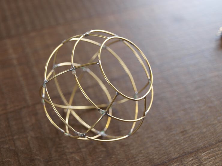
心愿球
由黃銅棒制成,采用自由球形態連接 18 顆發光 LED。制作出來的實物圖如下:

硬件材料
1*黃銅棒
18*貼片 LED
1*ATmega8L 芯片
1*CR2032 紐扣電池
1*開關
天體
主要挑戰是用黃銅棒彎成圓形,看起來像一個天體。我用 6 根銅棒豎直排列(經度)和 3 根銅棒
水平排列(緯度)構建一個球。這樣子就總共有 18 個交叉點用于焊接 LED。在球體的底部有一個
環形開口,為的是最終可以更好的放入芯片、電池等元器件。

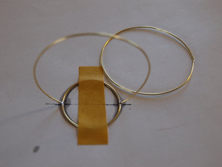
首先,把銅棒彎成圓形。我最開始找到一個直徑為 50 毫米的鐵罐,可以在彎曲時用底蓋固定銅
棒。彎曲銅棒后,把其剪斷并把兩端焊接在一起,形成一個漂亮的環。在一張紙上畫出相同的形
狀,可以幫助你匹配最完美的圓形。為了制作更小的圓環,我使用了其他直徑的瓶。使用與你的
直徑相匹配的東西,身邊上到處都是圓形的東西!
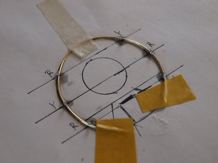
接下來,我把 LED 焊接到三個 50mm 環上。我在一張紙上畫了一個模板。我采用是黃色和紅色
LED。黃色和紅色,因為它比藍色或白色更節能。
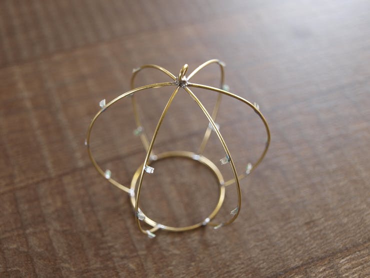
接著,我把帶有 LED 的環焊接到基環上。我用一塊膠帶把基環固定在桌子上,修剪了垂直環的底
部并把它們焊接到環上,形成了一個皇冠。第一個環焊接成一體,第二個和第三個環切成兩半,
形成球體的平頂。
最后一步是最讓人沮喪和耗時的。把 LED 與彎曲桿相互連接以形成水平環。我把剩下的環一個一
個地切開,以適應垂直環之間的空間并求佛一樣地焊接。
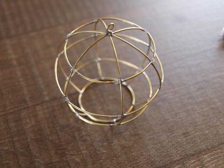
我想到一種放置 LED 的簡單方法。 兩個 LED 在鄰近的垂直環(地面)上彼此面對,它們與一根彎
曲的桿連接,該桿是水平環(電源線)的一部分。最終得到 18 個 LED,分為 9 個部分。
溫馨提醒:經常測試 LED 是否仍是好的,否則你需要在最后重做這件事,這是一種可怕的又振奮
人心的測試。
如果你只是希望它發光并且不關心任何動畫。你可以立即停止閱讀,把 CR2032 紐扣電池和開關放
入內部。通過 68Ω 限流電阻把 LED 與電池連接,就可以使其發光!把電池焊接到黃銅線時,請確
保不要過熱,否則可能會導致電池過熱。

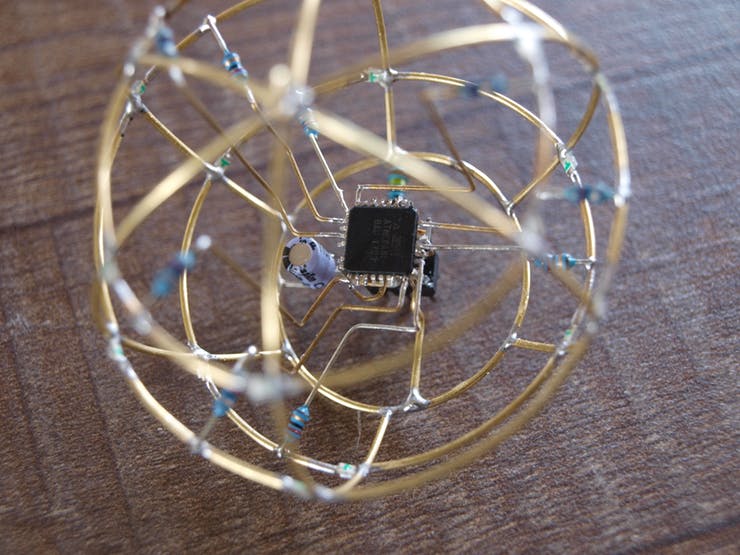
如果你像我一樣,愛 Arduino 并希望讓它變得聰明并且有一點樂趣,讓我們把微控制器放入其
中!我使用的是 ATmega8L 芯片——與 Arduino NANO 相同的封裝,但內存更少,功耗更低。L 意
味著它具有 2.7 - 5V 的寬工作電壓范圍,這在使用 3V 紐扣電池時非常棒。另一方面,由于它是
TQF32 封裝,因此焊接到銅棒上是一個不小的挑戰,但外觀和效果都很好。
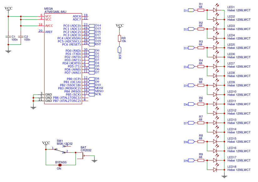
電路原理圖如下:
Arduino源代碼
- #define LEDS 9
- byte leds[] = {
- 5, 19, 17, // bottom
- 6, 1, 15, // middle
- 8, 21, 13 // top
- };
- #define ON true
- #define OFF false
-
- // variables for pattern timing
- unsigned long currentMillis = millis();
- unsigned long previousMillis = 0;
- unsigned long millisInterval = 3
- 00;
-
- // variables for software PWM
- unsigned long currentMicros = micros();
- unsigned long previousMicros = 0;
- // this is the frequency of the sw PWM
- // frequency = 1/(2 * microInterval)
- unsigned long microInterval = 250;
-
- const byte pwmMax = 100;
-
- // fading (for the timing)
- int fadeIncrement = 1;
-
- // typedef for properties of each sw pwm pin
- typedef struct pwmPins {
- int pin;
- int pwmValue;
- bool pinState;
- int pwmTickCount;
- } pwmPin;
-
- // create the sw pwm pins
- // these can be any I/O pin
- // that can be set to output!
- const int pinCount = 9;
- const byte pins[pinCount] = {
- 5, 19, 17, // bottom
- 6, 1, 15, // middle
- 8, 21, 13 // top
- };
-
- pwmPin myPWMpins[pinCount];
-
- // function to "setup" the sw pwm pin states
- // modify to suit your needs
- // this creates an alternating fade pattern
- void setupPWMpins() {
- for (int index=0; index < pinCount; index++) {
- myPWMpins[index].pin = pins[index];
-
- // mix it up a little bit
- // changes the starting pwmValue for odd and even
- if (index % 2)
- myPWMpins[index].pwmValue = 25;
- else
- myPWMpins[index].pwmValue = 75;
-
- myPWMpins[index].pinState = ON;
- myPWMpins[index].pwmTickCount = 0;
-
- // unlike analogWrite(), this is necessary
- pinMode(pins[index], OUTPUT);
- }
- }
-
- void pwmFadePattern() {
- // go through each sw pwm pin, and increase
- // the pwm value. this would be like
- // calling analogWrite() on each hw pwm pin
- for (int index=0; index < pinCount; index++) {
- myPWMpins[index].pwmValue += fadeIncrement;
- if (myPWMpins[index].pwmValue > 100)
- myPWMpins[index].pwmValue = 0;
- }
- }
-
- void handlePWM() {
- currentMicros = micros();
- // check to see if we need to increment our PWM counters yet
- if (currentMicros - previousMicros >= microInterval) {
- // Increment each pin's counter
- for (int index=0; index < pinCount; index++) {
- // each pin has its own tickCounter
- myPWMpins[index].pwmTickCount++;
-
- // determine if we're counting on or off time
- if (myPWMpins[index].pinState == ON) {
- // see if we hit the desired on percentage
- // not as precise as 255 or 1024, but easier to do math
- if (myPWMpins[index].pwmTickCount >= myPWMpins[index].pwmValue) {
- myPWMpins[index].pinState = OFF;
- }
- } else {
- // if it isn't on, it is off
- if (myPWMpins[index].pwmTickCount >= pwmMax) {
- myPWMpins[index].pinState = ON;
- myPWMpins[index].pwmTickCount = 0;
- }
- }
- // could probably use some bitwise optimization here, digitalWrite()
- // really slows things down after 10 pins.
- digitalWrite(myPWMpins[index].pin, myPWMpins[index].pinState);
- }
- // reset the micros() tick counter.
- digitalWrite(13, !digitalRead(13));
- previousMicros = currentMicros;
- }
- }
-
- void setup() {
- setupPWMpins();
- //pinMode(13, OUTPUT);
- }
-
- void loop() {
- // this is the magic for sw pwm
- // need to call this anytime you
- // have a long operation
- handlePWM();
-
- // check timer for fading pattern
- // this would be the same
- // if we used analogWrite()
- currentMillis = millis();
- if (currentMillis - previousMillis >= millisInterval) {
- // moved to own funciton for clarity
- pwmFadePattern();
-
- // setup clock for next tick
- previousMillis = currentMillis;
- }
- }
|


 QQ好友和群
 QQ空間
QQ空間 騰訊微博
騰訊微博 騰訊朋友
騰訊朋友 收藏
收藏 淘帖
淘帖 頂
頂 踩
踩

