|
|
TI的FDC2214電容傳感器最近參加電賽的同學(xué)都在用,分享一些資料給大家
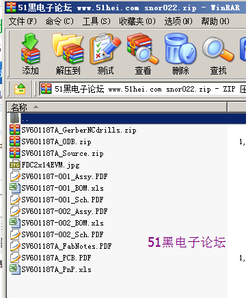
(包括原理圖,pcb,硬件統(tǒng)計等等)
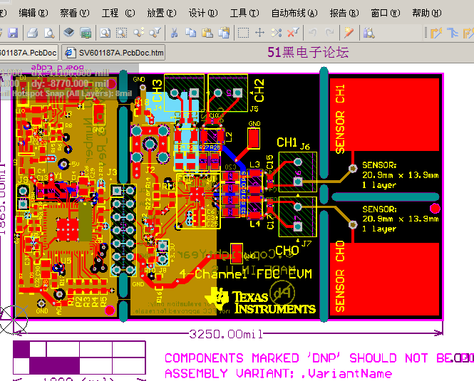
Altium Designer畫的原理圖和PCB圖如下:(51hei附件中可下載工程文件)
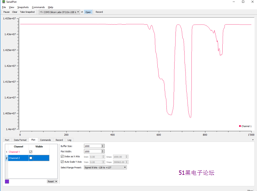
fdc-on-serialplot-signal
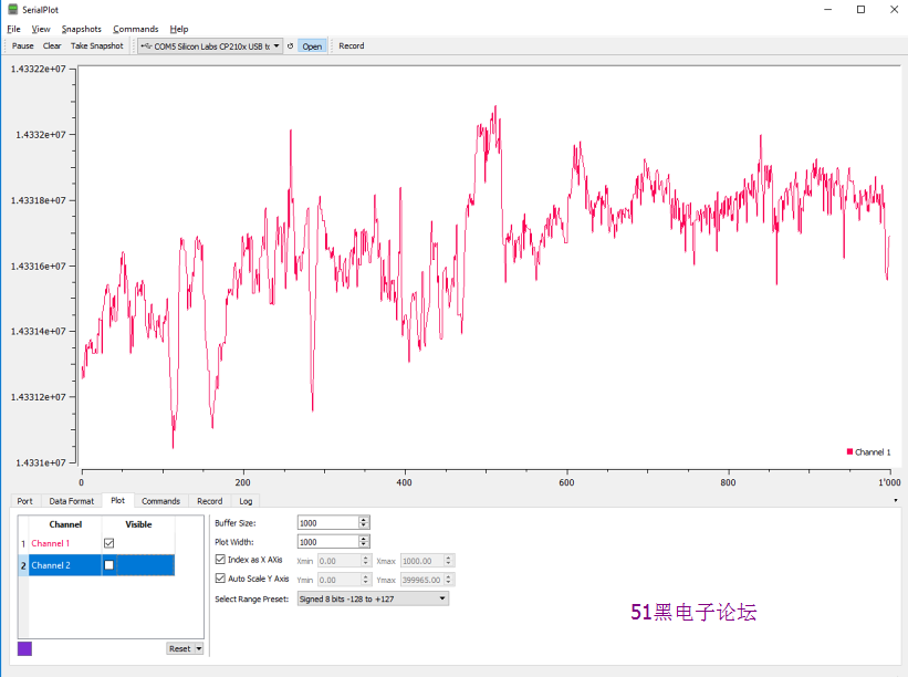
fdc-on-serialplot-noise
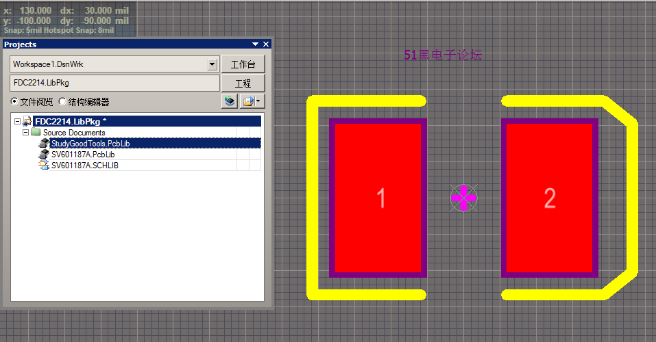
封裝庫:
基于Arduino程序(測試通過)
- //
- // FDC2x1x hardware configuration:
- // Component value as in default circuit form datasheet. (18uH inductor and 33pF cap)
- //
- // SD and ADDR pins tied to GND
- // INTB pin not used
- //
- // ARDUINO <--> FDC
- // A4 <-------> SDA
- // A5 <-------> SCL
- //
- // !!!!!! Arduinos are mostly 5V. FDC chips are 3.3V, so either use 3.3V version of Arduino, like pro mini, or use level shifter on I2C bus.
- //
- // ### FDC
- #include <Wire.h>
- #include "FDC2214.h"
- FDC2214 capsense(FDC2214_I2C_ADDR_0); // Use FDC2214_I2C_ADDR_1
- // ###
- void setup() {
-
- // ### Start I2C
- Wire.begin();
- // Wire.setClock(400000L);
-
- // ### Start serial
- Serial.begin(115200);
- Serial.println("\nFDC2x1x test");
-
- // ### Start FDC
- // Start FDC2212 with 2 channels init
- bool capOk = capsense.begin(0x3, 0x4, 0x5); //setup first two channels, autoscan with 2 channels, deglitch at 10MHz
- // Start FDC2214 with 4 channels init
- //bool capOk = capsense.begin(0xF, 0x4, 0x5); //setup all four channels, autoscan with 2 channels, deglitch at 10MHz
- if (capOk) Serial.println("Sensor OK");
- else Serial.println("Sensor Fail");
- }
- // ### Tell aplication how many chanels will be smapled in main loop
- #define CHAN_COUNT 2
- // ###
- void loop() {
- unsigned long capa[CHAN_COUNT]; // variable to store data from FDC
- for (int i = 0; i < CHAN_COUNT; i++){ // for each channel
- // ### read 28bit data
- capa[i]= capsense.getReading28(i);//
- // ### Transmit data to serial in simple format readable by SerialPlot application.
- Serial.print(capa[i]);
- if (i < CHAN_COUNT-1) Serial.print(", ");
- else Serial.println("");
- }
- // No point in sleeping
- //delay(100);
- }
全部資料51hei下載地址:
 6.封裝庫.zip
(624.1 KB, 下載次數(shù): 143)
2018-7-6 13:12 上傳
點擊文件名下載附件
 1.基于Arduino程序(測試通過).zip
(84.43 KB, 下載次數(shù): 129)
2018-7-6 13:12 上傳
點擊文件名下載附件
 snor022.zip
(4.04 MB, 下載次數(shù): 136)
2018-7-6 13:11 上傳
點擊文件名下載附件
|
評分
-
查看全部評分
|
